
Aluminum cut face squareness describes an end face’s relationship to the reference required by the drawing. Identify the face, its datum and the agreed inspection method. A correct finished length does not, by itself, establish that the end face has the required orientation.
For a part requiring a square end, keep length and end-face checks separate in the trial record. For a deliberately angled end, inspect the specified angle instead. Use the actual drawing requirements rather than a generic description such as clean cut.
Make the end requirement clear
- Identify the end face and its required reference.
- Keep length, orientation and surface condition separately recorded.
- Use a suitable agreed method for the actual geometry and tolerance.
On this page
1. Identify the face in an aluminum cut face squareness review
Mark the end being reviewed and the relevant drawing requirement. A hollow extrusion can have several separate walls on the cut face. Show which surfaces or features the inspection needs to represent.
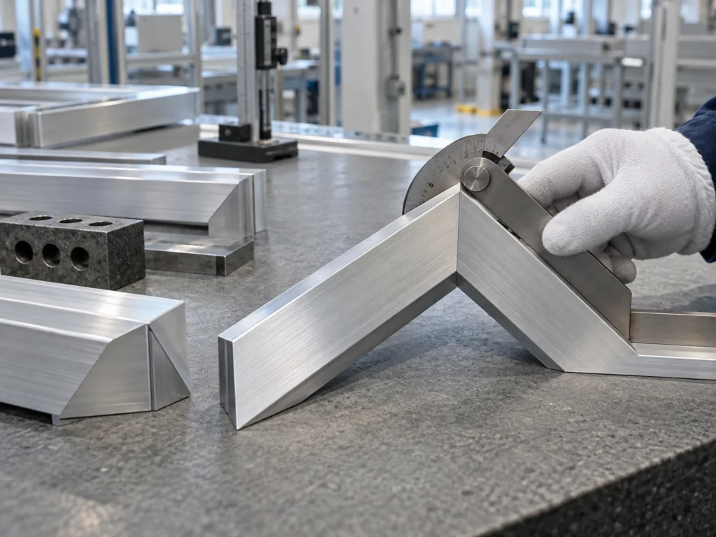
Distinguish a square-ended part from one with a deliberate miter. A 90° assembly corner can be formed from angled ends; that does not make each end a square cut. Follow the individual part drawing as well as the assembly definition.
Separate end-face orientation from surface appearance. Saw marks, burrs and visible edges provide different observations. A smooth-looking end can still require dimensional review, while a dimensional result does not establish every surface requirement.
For an intermediate blank, identify which requirements apply before later machining. The saw and machining-center guide explains why the final drawing and the saw handoff can describe different stages.
2. Agree which reference defines the relationship
Use the datum or reference identified on the approved drawing. Do not assume that the easiest exterior face to contact is the required reference. Grooves, projecting flanges or an asymmetric section can make that assumption misleading.
Mitutoyo’s measurement guide illustrates perpendicularity relative to a datum and a defined tolerance zone. That is why the reference belongs in the inspection definition. This article does not supply a substitute tolerance or reinterpret your drawing’s applicable standard.
Keep the length datum visible too. The chosen points for a finished-length measurement can be different from the features used to establish an end’s orientation. Write both clearly rather than using one ambiguous reference description.
If the drawing leaves the relationship unclear, resolve it with the responsible drawing owner. A machine display showing a nominal cut position is a setup observation; it is not a measurement of the finished face relative to the required datum.
3. Define the inspection before the sample trial
Agree the method, instrument, contact locations and way the reference is established. The method needs to suit the geometry and specified requirement. A thin hollow wall, an interrupted face and a solid block can present different contact conditions.
Record how the sample is supported and how the identified reference is used. Keep the method consistent across the samples being compared. If a contact changes between readings, retain that information rather than attributing every difference to the saw.
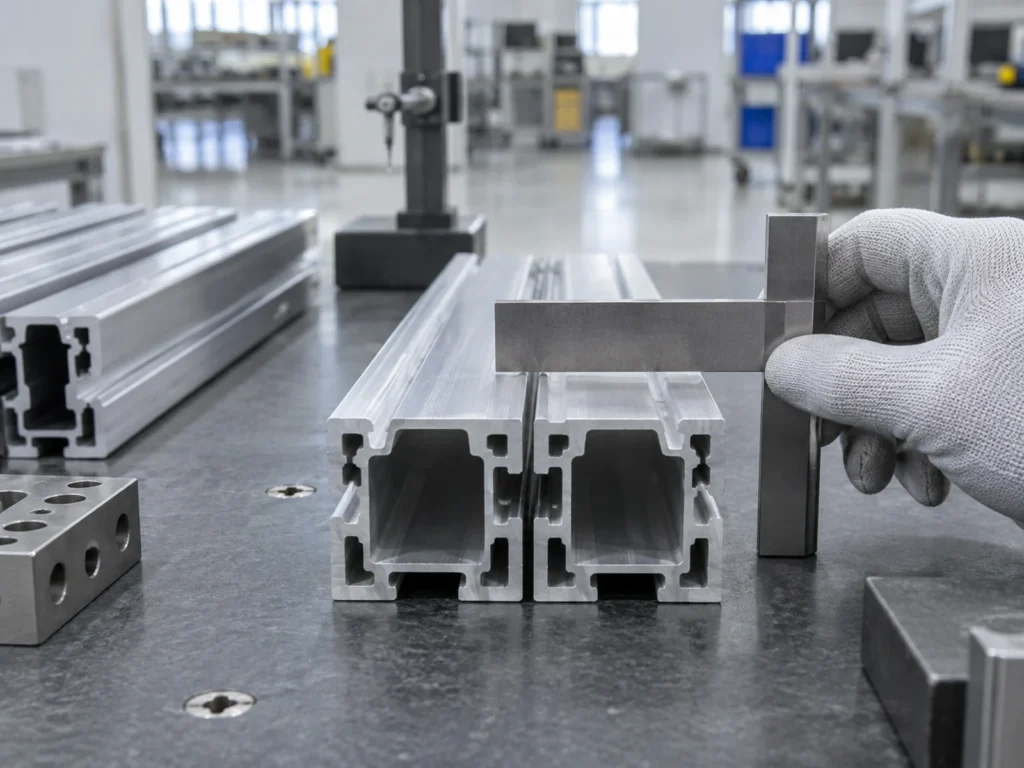
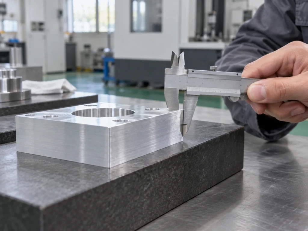
A square can support an appropriate comparison, but a photograph of it beside a part does not provide a numeric tolerance result. Likewise, one caliper contact does not establish the orientation of the full face. Use the agreed inspection method for release.
Keep readings separate from the decision. The drawing tolerance guide explains why measured values and permitted limits are different records. No universal squareness limit is supplied here.
An 80 mm example: a small angle creates an end offset
Illustrative ideal geometry: view one straight, flat end line in two dimensions across an 80 mm profile width. Suppose the line is tilted 0.2° from the intended square end direction. The numbers are invented to explain geometry, not a machine test or acceptable tolerance.
The longitudinal difference between the line’s two edge positions is approximately 80 × tan(0.2°) = 0.279 mm. Rounded for explanation, the offset is about 0.28 mm across that 80 mm width.
This is a geometric edge-position difference in the chosen view. It is not automatically the result of a drawing’s perpendicularity inspection, which depends on the defined features, datum and evaluation. Do not replace the actual requirement with this calculation.
The same angle produces a different edge offset across a different width. That helps explain why a trial should include representative sections and the required cut position. A demonstration on one small sample does not describe every profile family.
Why matching lengths can hide two tilted ends
Consider the ideal two-dimensional example again, now with both end lines tilted by the same amount in the same direction. The ends are parallel to each other. Neither line has the intended square orientation relative to the longitudinal reference.
Choose a longitudinal length of 500 mm between the two lines at one edge. Because the lines are parallel, the longitudinal separation at the other edge can also be 500 mm. Comparing those two lengths alone does not expose the shared tilt.
If one end is square and the other carries the example’s tilt, the edge lengths can differ by about 0.28 mm. Those two situations produce different length observations. Keep the end orientation review separate instead of relying on a single comparison rule.
These examples describe ideal straight lines, not a practical gauge setup or a verified extrusion. Actual cut faces can include surface variation and interrupted walls. The real inspection must represent the required geometry through its agreed method.
The miter length guide provides related long- and short-point examples. Those calculations clarify length references; they do not replace the end-angle or perpendicularity checks required for a finished part.
Build a trial record that separates the observations
Identify the sample
Record the part identity, drawing revision, section, source material and tested configuration. Mark which end is being reviewed. Keep samples from different setup conditions in identifiable groups.
Record the required result
List the finished-length requirement, end-face relationship and applicable cut-face or edge requirements separately. Use the drawing’s defined limits and references. Retain any unresolved interpretation before treating the review as ready.
Record the observations
Keep the length readings, orientation evaluation and surface observations with their methods. A result that satisfies one item should not erase an open question in another. Include both ends when the job requires them to be checked.
Make the release decision visible
Compare the relevant results with the agreed requirements through the responsible quality process. Record any held samples and the reason. The batch traceability guide explains how that status stays connected to the physical part group.
Use a drawing-based brief for machine selection
When reviewing the JiurunCut machine range, include the complete section and finished-part drawings. Describe the end references, length range and required inspection evidence. Request a representative trial using the proposed configuration.
Send the profile drawings and end-face requirements for review. This guide helps define the question; it does not claim a model-specific squareness, accuracy or capability. Agree the actual test conditions and acceptance requirements before drawing a production conclusion.
Common questions
Does the correct length prove the end is square?
No. Length is measured between specified references. End-face orientation is a separate relationship. Two equally tilted parallel ends can retain matching longitudinal lengths at different edges in ideal geometry.
Is a 90° assembled corner proof of square-cut ends?
No. An assembly corner can use deliberately mitered parts. Review the angle and reference required on each individual part drawing as well as the assembled relationship.
Can I use the 0.28 mm example as an acceptance limit?
No. It is an illustrative geometric offset across a chosen width. The approved drawing and inspection definition establish the applicable requirement and evaluation.
What should I send for a sample review?
Provide the section and finished-part drawings, required datums, limits, material identity and relevant cut positions. Agree the methods and representative samples with the supplier and responsible quality team.