
Aluminum miter cut length must identify the edge being measured. On a simple member with inward 45° cuts at both ends, the short-edge length equals the long-edge length minus twice the width in the cutting plane.
For an invented 1,200 mm long edge and 40 mm width, that gives 1,120 mm along the short edge. The calculation describes finished geometry. It does not include saw kerf, trimming or the machine’s stock-handling requirements.
Three things to remember
- Mark long and short edges on the finished-part drawing.
- Use the width in the actual cutting plane, not an unrelated section dimension.
- Plan raw stock separately from the finished geometry calculation.
On this page
Which edge defines aluminum miter cut length?
Imagine looking straight down at a rectangular strip. One long edge runs between the two outer tips of the angled ends. The opposite edge runs between the two inner tips. With both ends angled inward, those two distances are different.
Name the required distance on the drawing: long edge, short edge or another explicitly defined reference. Do not use “overall length” and expect everyone to infer the same endpoints. Show the cut directions and identify the reference edge with a dimension line.
The Aluminum Association describes its extrusion drafting publication as a resource for consistent profile drawings. This article offers a limited geometry example. Your approved finished-part drawing remains the instruction for the actual component.
For asymmetric profiles, identify the physical face shown in the dimensioned view. A rotated part can look similar while presenting a different width to the angled cut. Mark an orientation feature so the view, setup review and inspection record refer to the same face.
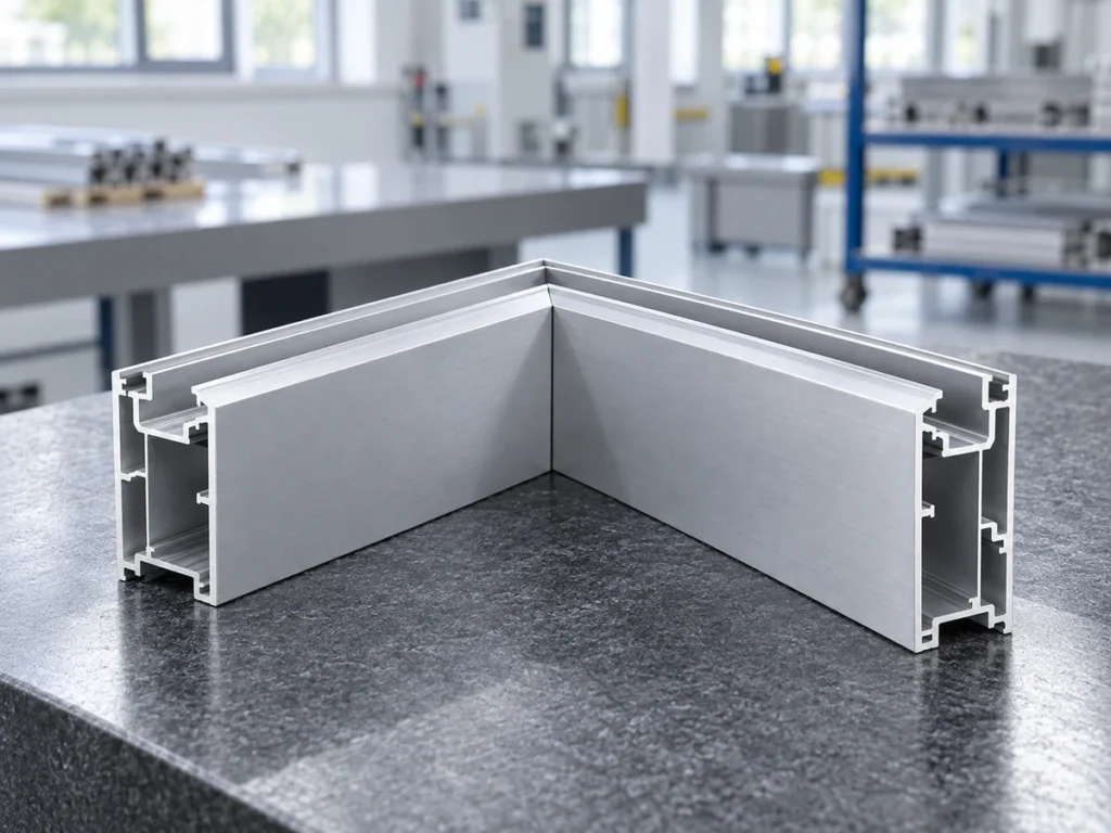
A 45° example: 1,200 mm long edge and 40 mm width
Use these invented inputs: a straight rectangular member, 40 mm wide in the cutting plane, with two opposing inward cuts. Each cut face lies at 45° to the member’s longitudinal edge in this view. The long edge is specified as 1,200 mm.
At 45°, the right triangle formed across the width has equal perpendicular legs. A 40 mm transverse width therefore gives a 40 mm longitudinal setback at each end. This is a geometric relationship, not a machine display setting or production allowance.
- Left-end setback: 40 mm.
- Right-end setback: 40 mm.
- Total difference between edges: 40 + 40 = 80 mm.
- Short-edge length: 1,200 − 80 = 1,120 mm.
The same piece can correctly measure 1,200 mm on one edge and 1,120 mm on the opposite edge in this ideal example. If two people use different edges, their readings disagree by 80 mm without necessarily describing different parts.
If the drawing instead specifies the short edge as 1,120 mm, the same geometry gives a 1,200 mm long edge. The arithmetic goes in the opposite direction. Keep the specified dimension visibly marked so nobody treats a calculated reference as the production requirement.
What changes with one angled end or another orientation?
For the same 40 mm wide strip with one square end and one 45° end, only one end contributes a setback. An invented 1,200 mm long edge would then correspond to a 1,160 mm short edge. The square end contributes no long-to-short difference.
Do not apply the two-setback subtraction to every part with two angled ends. With parallel angled ends, the opposing edge offsets can cancel, giving equal edge lengths in the ideal rectangular view. Compound cuts and unequal angles require their own geometry.
Our calculation applies only to the defined planar shape and cut directions. Grooves, lips, rebates or protruding features may create additional visible points. Identify the actual dimension endpoints rather than choosing whichever tip seems easiest to reach.
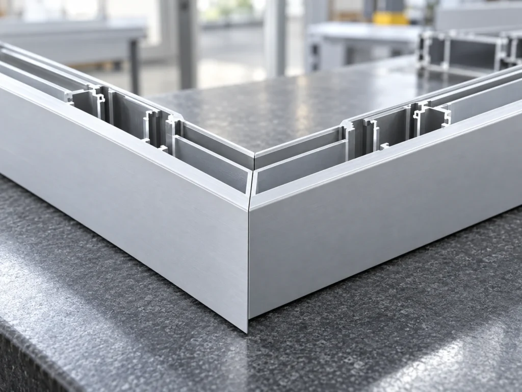
Why is finished geometry different from raw stock use?
The 1,200 mm long edge describes the finished member. It does not automatically tell you how much incoming stock is consumed. Stock planning also depends on cut sequence, initial trimming, blade cutting width and the approved way to support and hold the remaining material.
Do not add blade kerf to the short-edge conversion. The 80 mm difference in our example comes from the two angled ends across a 40 mm width. Kerf belongs in the separate material-removal calculation for the actual sequence of cuts.
For an angled cut, the blade’s cutting width and the length of stock affected along the feed direction need a defined relationship. Do not copy a straight-cut allowance into an angled cut list without reviewing the blade plane and sequence with the supplier.
Ask whether every member receives two separate end cuts, whether a cut can form an end for another part, and when the cut direction changes. These details affect material planning. They should not be inferred from a photograph of a finished frame.
The straight-cut kerf and stock-length example explains a length balance for its stated cut sequence. For mitered work, prepare the actual angled-cut sequence before estimating yield. Keep machine-specific gripping and remaining-stock limits as supplier-confirmed inputs.
What should the review drawing show?
Use a dimensioned finished-part view and a section view. Together they show which material dimension crosses the cutting plane and where the finished length starts and stops. Include the revision so an older sketch cannot silently replace the current requirement.
| Drawing item | Question it answers |
|---|---|
| Reference edge | Which endpoints define the specified finished length? |
| Cut direction | Are the ends opposing, parallel or different? |
| Section orientation | Which width lies in the cutting plane? |
| Angle definition | Which faces or lines define the angle shown? |
| Acceptance criteria | What dimensions and joint conditions must the sample meet? |
Add quantities and mirrored identities where relevant. If two members have the same length but opposite orientations, give them distinct identities. A cut list containing only “1,200 mm, 45°” leaves important geometry unresolved.
The broader aluminum miter cutting guide covers joint planning and machine configuration questions. Use this length example to clarify the drawing before discussing the equipment needed for the complete job.
How should the sample pieces be checked?
Measure the dimension required by the approved drawing using its agreed endpoints and method. Record the piece identity and orientation beside the result. Checking a different edge can produce a valid reading that does not answer the acceptance question.
Inspect the cut angle separately. For an assembly, review the intended joint using representative mating pieces. A closed-looking seam does not replace the length and angle checks required for each member.
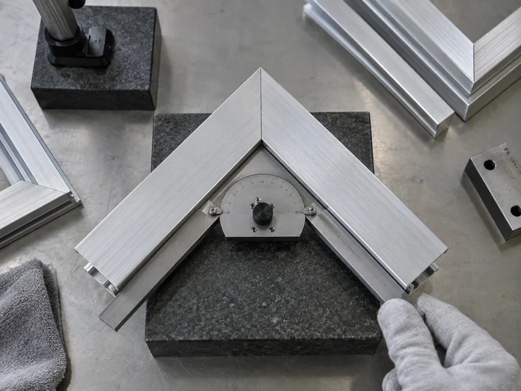
Our exact 1,120 mm result assumes ideal dimensions and ideal 45° geometry. Real parts have specified permitted variations. Evaluate measured pieces against the applicable drawing requirements; do not create an acceptance limit from the arithmetic example.
If the results disagree, first confirm that the two records use the same endpoints, orientation and drawing revision. Then review the observed part and setup through the approved process. A discrepancy alone does not identify a machine fault.
Common questions
Should aluminum miter cut length always use the long edge?
Use the edge or reference specified by the approved drawing. The long edge may be convenient in some designs, but convenience does not override the dimension requirement. Make that reference clear in the inquiry and inspection method.
Does 40 mm mean the overall height of the extrusion?
Here it means the transverse width in the defined cutting plane. An extrusion’s height, width and local feature dimensions can differ. Use the view and orientation that describe the actual angled cut.
Does a machine’s 45° display match this angle definition?
Confirm how the equipment defines its angle and positions the profile. This example defines geometry between a cut face and a longitudinal edge. It is not an instruction to enter a particular value on an unverified machine.
Can I use this formula for a compound cut?
No. The example is a simple planar rectangular shape with specified opposing 45° ends. Compound cuts, different angles and different reference features need the appropriate drawing or geometry review.
Send a dimensioned miter-cutting requirement
Share the section drawing, finished-length reference, end directions, angle definitions and batch quantities with JiurunCut. We can discuss the cutting arrangement and a sample review that matches your actual members.