
Aluminum cutting tolerance describes the specified limits for a defined cut dimension. Read the dimension, units, reference faces and applicable drawing notes together. Convert the stated deviations into a lower and upper limit before discussing a machine or sample result.
A drawing requirement, a quoted machine claim and a measurement result answer different questions. Keep them separate so the supplier knows what the part must meet and how the trial will be reviewed.
A quick way to read the requirement
- Identify the dimension and its reference surfaces.
- Calculate the lower and upper specified sizes.
- Agree the measurement and release process.
On this page
Define the aluminum cutting tolerance before comparing machines
Start with the exact dimension on the current drawing. A finished length between two specified faces is different from the extrusion’s section height or width. An angle requirement is another check. One satisfactory length reading does not establish all three.
For angled parts, identify whether the length relates to long points, short points or another drawing reference. The miter length example shows how those references can produce different numbers on the same idealized part.
NIST distinguishes engineering tolerances from statistical tolerance intervals. Engineering limits come from the specification; a statistical interval describes a population using data and assumptions. A sample’s observed spread does not rewrite the drawing limits.
Check whether an individual dimension has its own limits or is governed by an applicable general note. Resolve an unclear requirement with the drawing owner. Avoid importing a familiar tolerance from a previous part or a machine advertisement.
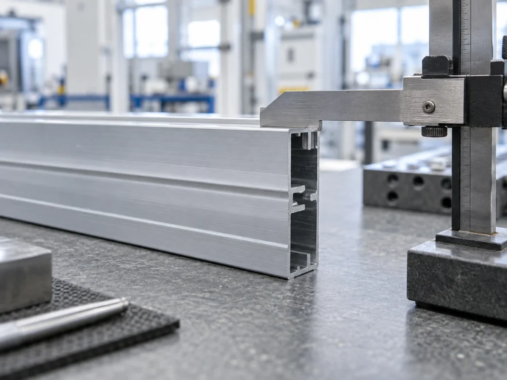
Example 1: 500.00 mm ±0.20 mm
Illustrative arithmetic: the drawing states 500.00 mm with an equal deviation of 0.20 mm in either direction. These values explain how limits are calculated. They are not a JiurunCut machine rating or a recommended tolerance for your design.
- Lower limit: 500.00 − 0.20 = 499.80 mm.
- Upper limit: 500.00 + 0.20 = 500.20 mm.
- Total specified size range: 500.20 − 499.80 = 0.40 mm.
The plus/minus value is 0.20 mm, while the total range is 0.40 mm. Calling both numbers “the tolerance” without further explanation can cause a quotation misunderstanding. State the two limits in the trial brief as well as the original drawing notation.
An indicated reading of 500.10 mm falls numerically between these limits. A reading of 500.25 mm is numerically above the upper limit. That comparison explains arithmetic only; the actual release decision also uses the agreed measurement and decision process.
Example 2: 500.00 mm, +0.30 / −0.00 mm
This illustrative requirement allows an increase from the stated 500.00 mm size and no decrease. The lower limit is 500.00 mm. The upper limit is 500.30 mm. The total specified size range is 0.30 mm.
It is not equivalent to 500.00 mm ±0.30 mm. The latter calculation would give a lower limit of 499.70 mm and an upper limit of 500.30 mm. The lower limits and total ranges are different.
An indicated 499.95 mm reading is numerically below the one-sided example’s lower limit, even though it is close to 500.00 mm. “Close to nominal” is not a substitute for reading both limits.
Do not change the drawing to a symmetric expression for convenience. Any proposed requirement change needs the responsible drawing owner’s review. Programming targets and process adjustments are separate decisions from interpreting the stated limits.
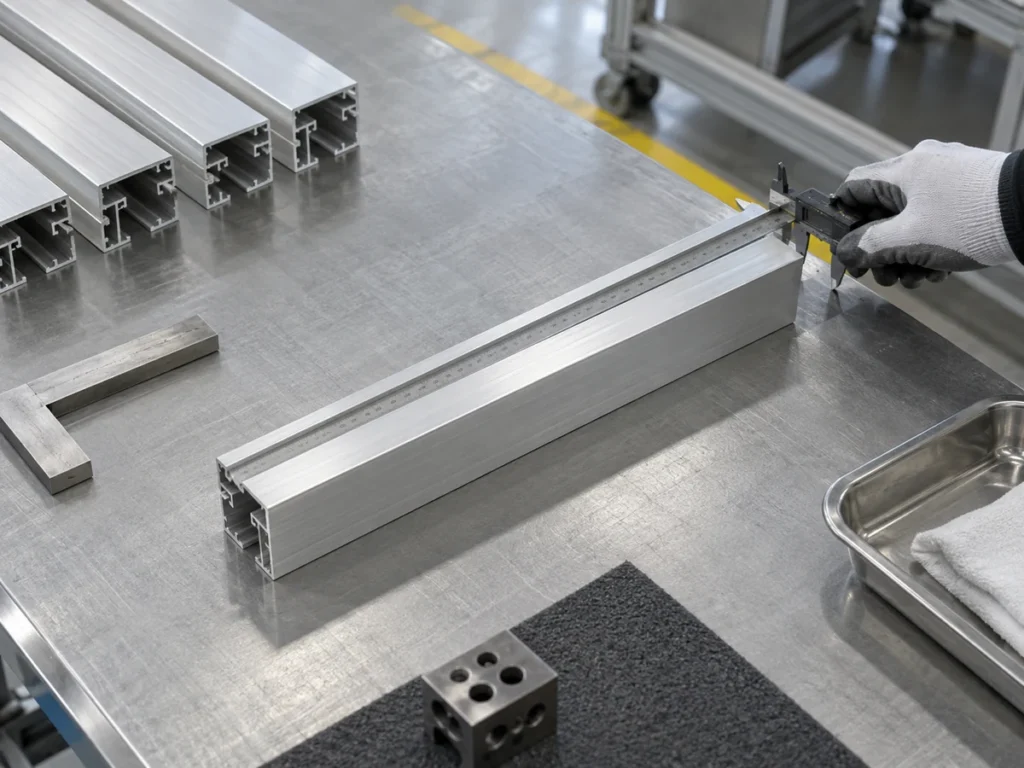
Example 3: limit sizes of 499.90 mm and 500.10 mm
In this example, the two limit sizes are supplied directly. The lower limit is 499.90 mm and the upper limit is 500.10 mm. Their difference is 0.20 mm.
The midpoint is 500.00 mm. The same two numerical limits can be written as 500.00 mm ±0.10 mm. That calculation does not authorize changing the drawing’s presentation, inspection rules or programming target.
Keep the units and decimal values intact when transferring the requirement into a cut list or quotation. For a drawing expressed in another unit, agree the conversion and reporting process instead of mixing units in one record.
Read the measurement result separately from the limits
A result needs to identify what was measured and how. Include the part identity, drawing revision, reference surfaces, units and relevant method. A number without that context can be impossible to compare with the requirement.
NIST’s measurement uncertainty overview explains that uncertainty describes the dispersion of values reasonably attributable to the measured quantity using the available information. It is associated with the measurement result, rather than being an extra allowance in the drawing.
For example, an instrument displaying two decimal places does not establish that the entire measurement process has an uncertainty of 0.01 mm. Displayed digits, the suitability of the method and the reported uncertainty are different matters.
Agree how results near a specification limit will be evaluated. Do not automatically add measurement uncertainty to the allowed part size or silently subtract it using an improvised rule. The responsible inspection process should define the decision.
If repeated readings disagree, keep the original observations and relevant conditions available for review. Do not choose the most convenient reading as the final result. A photograph of a caliper is also insufficient to establish a released dimension.
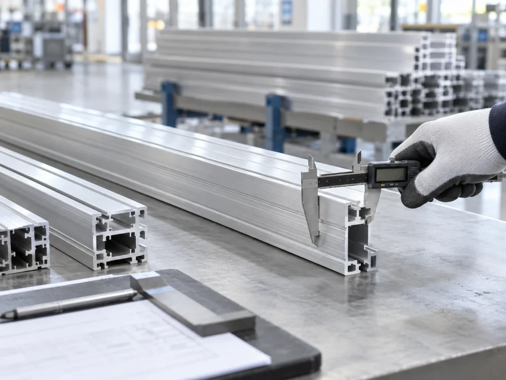
Keep machine claims, part limits and repeatability distinct
A quoted accuracy value needs its stated scope and test conditions. Ask what dimension was checked, what material and configuration were used and how the result was obtained. A number presented without those details cannot confirm your drawing requirement.
Repeatability describes consistency under the defined repeated conditions. Consistent pieces can still differ from the required size. Likewise, one piece near the nominal value does not establish consistent output over a production batch.
The 12-part length drift example demonstrates why the sequence of readings matters. Use the record to support a review; an observed range alone does not identify a cause or demonstrate that a process will satisfy every future batch.
| Question | Record to review |
|---|---|
| What does the part require? | The current drawing and applicable specification limits. |
| What does the offer claim? | The quoted configuration, performance definition and test conditions. |
| What did the trial show? | The identified samples, measurement results and agreed review process. |
Write a clear trial brief
Send the supplier the drawing and mark the dimension being reviewed. Include both specified limits, the reference faces and the applicable notes. Keep requirements for length, angle, cut face and visible surfaces separately identifiable.
Describe the profile section, material identification, finish, quantities and representative part lengths. Define whether the saw delivers a finished part or an intermediate blank. A later machining operation can change which dimensions the cutting stage must produce.
Agree the sample identification, measurement method, reporting and acceptance process before the trial. Ask for individual results linked to the samples rather than a general statement that the parts look accurate. Record any requirement that remains unresolved.
Use the JiurunCut product range to identify a candidate cutting configuration, then send the marked drawing for review. Confirm suitability through a relevant quotation and trial; the example values in this guide do not establish model-specific capability.
Common questions
Does ±0.20 mm mean a total range of 0.20 mm?
No. In the symmetric 500.00 mm example, the limits are 499.80 mm and 500.20 mm. Their difference is 0.40 mm. State both the deviation and the limits to avoid confusion.
Can I accept a part because the average length is nominal?
A nominal average does not establish that every required dimension meets its limits. Review the individual results and the applicable inspection plan. A high and a low result can produce a nominal average.
Does a machine’s advertised accuracy replace the drawing tolerance?
No. The drawing defines the required part limits. Review the machine claim and its test conditions separately, then agree how a representative trial will be checked against the actual requirements.
What if my drawing only says 500 mm?
Review the applicable drawing notes and referenced requirements. If the limits or references remain unclear, resolve them with the drawing owner before quoting, programming or accepting the part. Do not assume an arbitrary plus/minus value.