
01
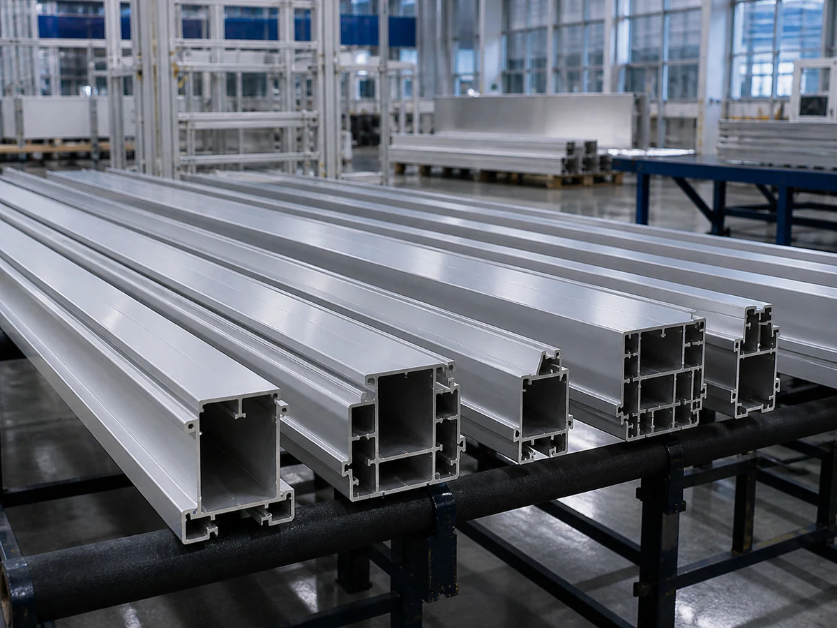
Battery-Box Side Rails
CHALLENGE
Thin walls, local cavities and joint alignment.
WHAT WE REVIEW
Section support · clamp contact · finished length · mating reference
Send Battery-Box DrawingENERGY STORAGE ALUMINUM CUTTING ENGINEERING
Send your profile sections and available cutting list. JiurunCut reviews stock length, finished lengths, quantities, support and clamping before proposing a machine configuration and sample-cutting plan.
Start with: Profile sections · Stock length · Finished lengths · Quantities · Assembly datum
01 — UNDERSTAND THE PART
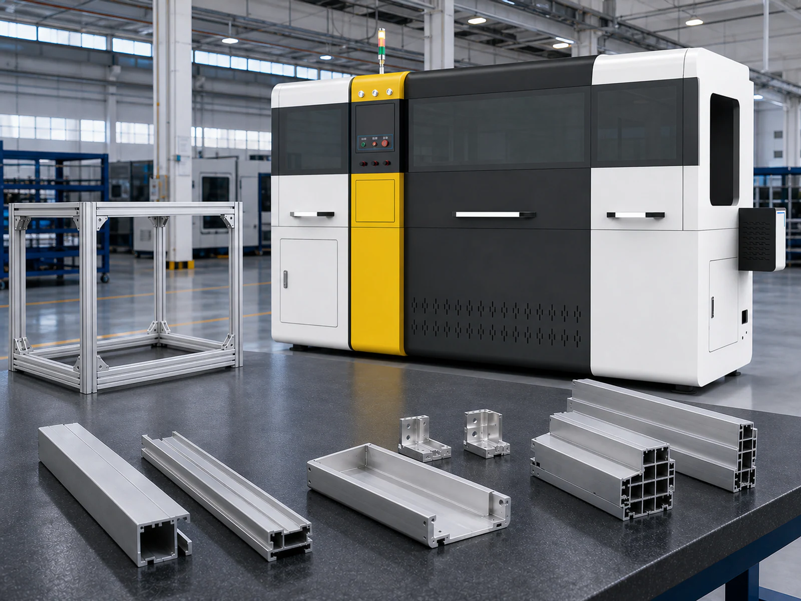
ENGINEERING INPUTS
Cross-section · wall thickness · profile family
Mating surface · finished length · inspection origin
Stock length · finished lengths · quantities
Batch mix · kit identification · production target
BUYER FIT
Start with the frame members and the lengths that must fit together.
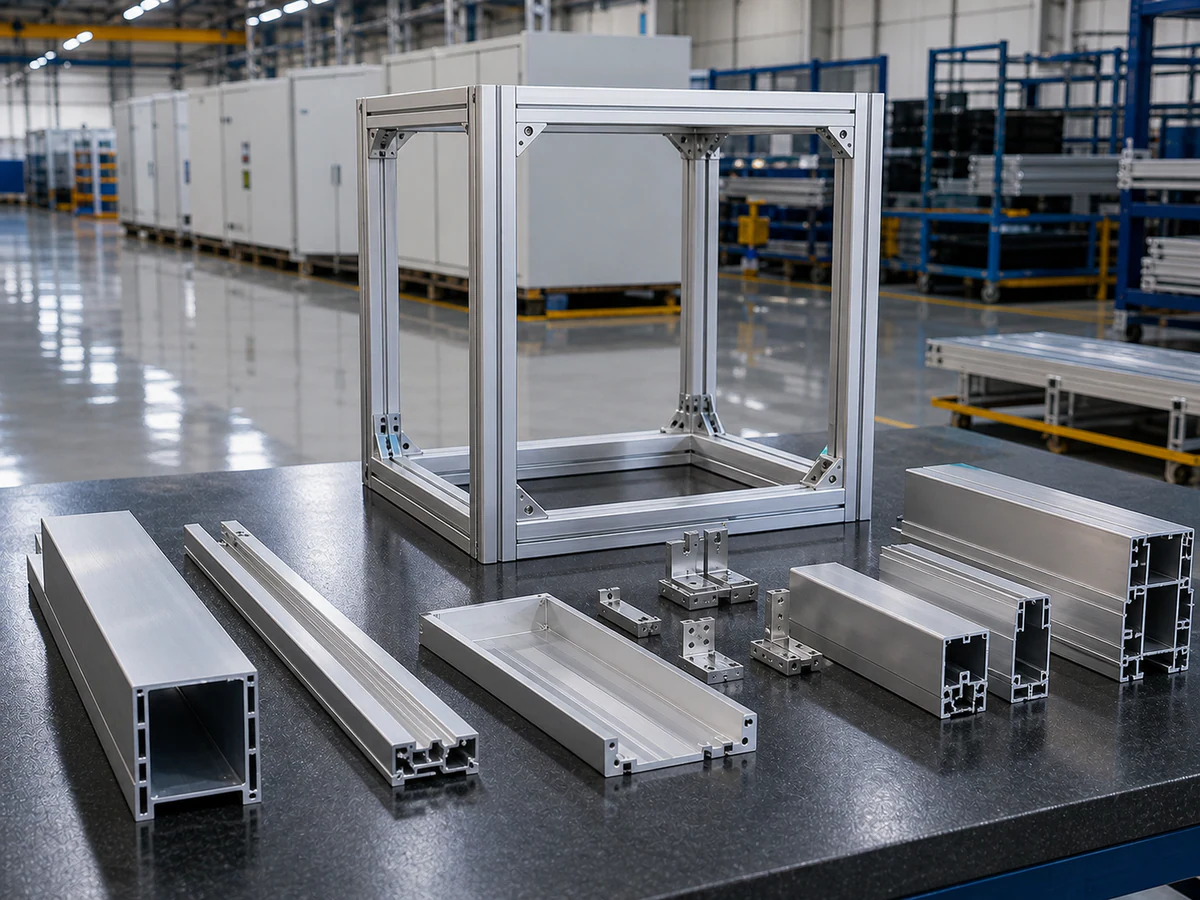
PACK frame members, battery-box side rails, cabinet uprights and mixed-length frame kits.
Assembly datum, profile-family changeover, finished lengths and visible surfaces.
Profile-specific support, controlled feeding and clamping, circular-saw cutting and inspection.
Selected after reviewing the real sections, stock and finished lengths, quantities and handling requirements.
Section and frame drawings, stock length, available cut list, tolerances and production target.
TYPICAL ENERGY STORAGE PARTS
Profile geometry and frame-kit requirements determine support, clamping, datum and cutting sequence.
CHALLENGE
Thin walls, local cavities and joint alignment.
WHAT WE REVIEW
Section support · clamp contact · finished length · mating reference
Send Battery-Box Drawing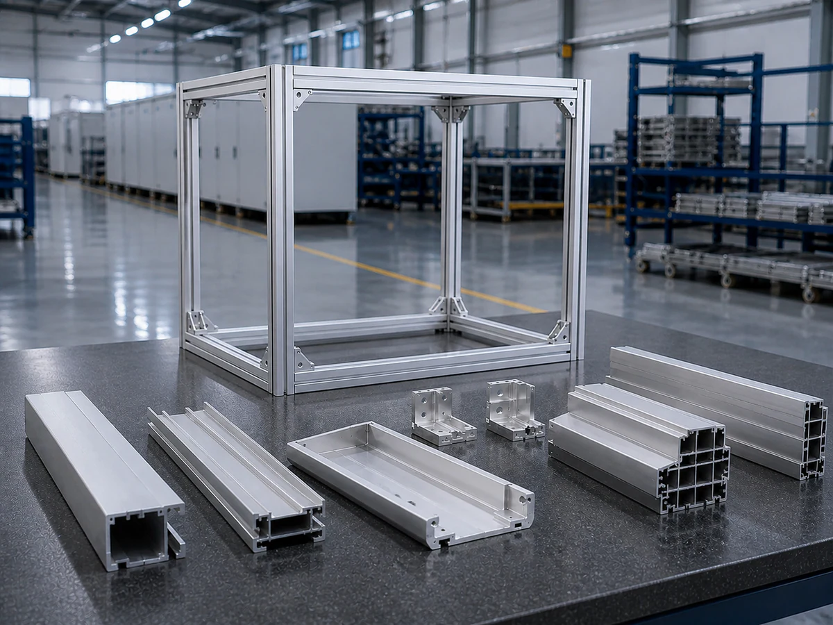
CHALLENGE
Connection faces and repeatable member lengths.
WHAT WE REVIEW
Assembly datum · wall support · finished lengths · frame fit
Send PACK Frame Drawing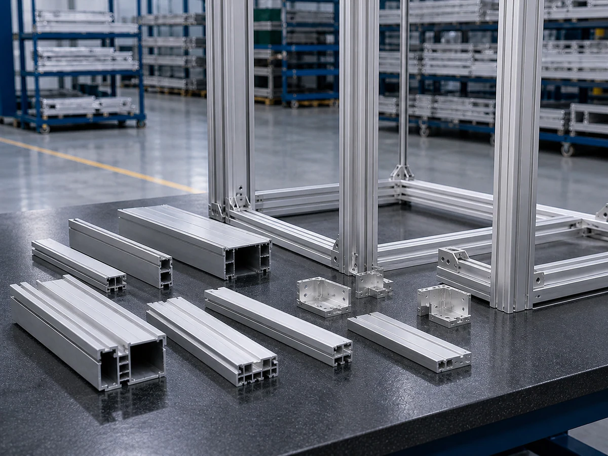
CHALLENGE
Visible faces and consistent connection points.
WHAT WE REVIEW
Surface protection · support · feed-to-collection contact
Send Cabinet Profile Drawing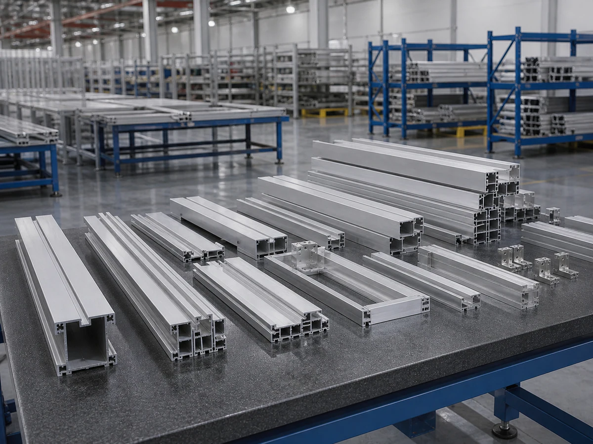
CHALLENGE
Several finished lengths and quantities in one delivery kit.
WHAT WE REVIEW
Full cut list · changeover · part identification · kit sequence
Send Your Frame Cut ListENGINEERING DECISIONS
Review the profile family and production list together before selecting the cutting direction.
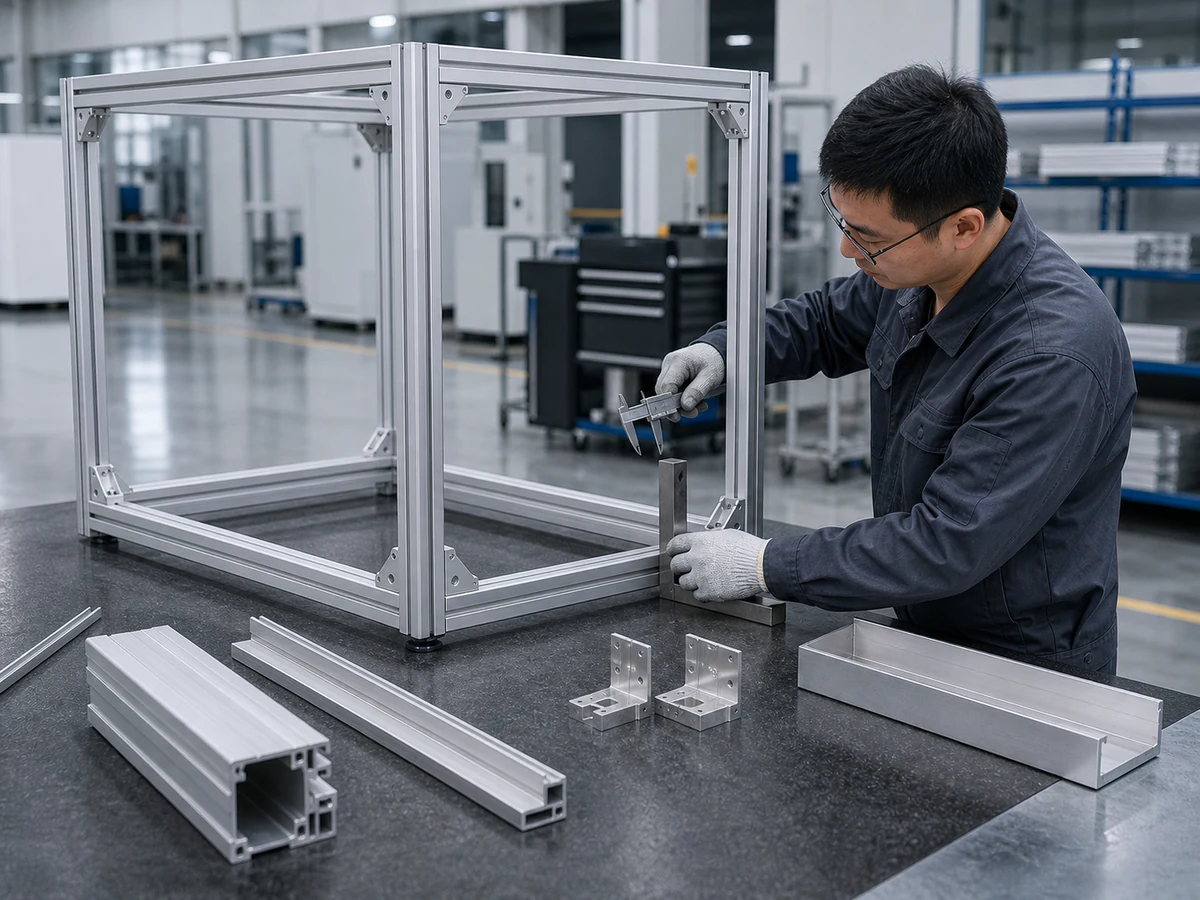
THE RISK
A correct overall length can still leave a joint out of position.
JIURUN ENGINEERING RESPONSE
Identify the mating face and align support, positioning and measurement; verify representative frame fit.
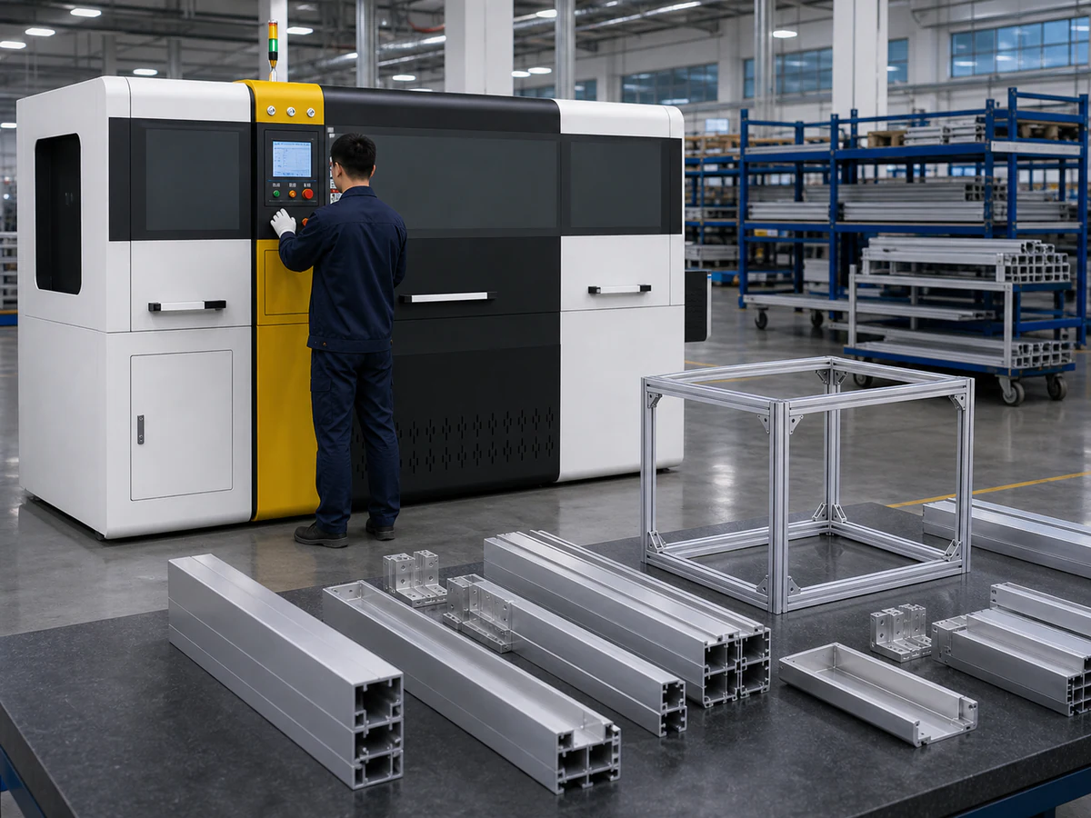
THE RISK
Different cavities and wall strengths may not share one fixture.
JIURUN ENGINEERING RESPONSE
Group sections by support and clamping compatibility; verify stable holding and repeatable setup.
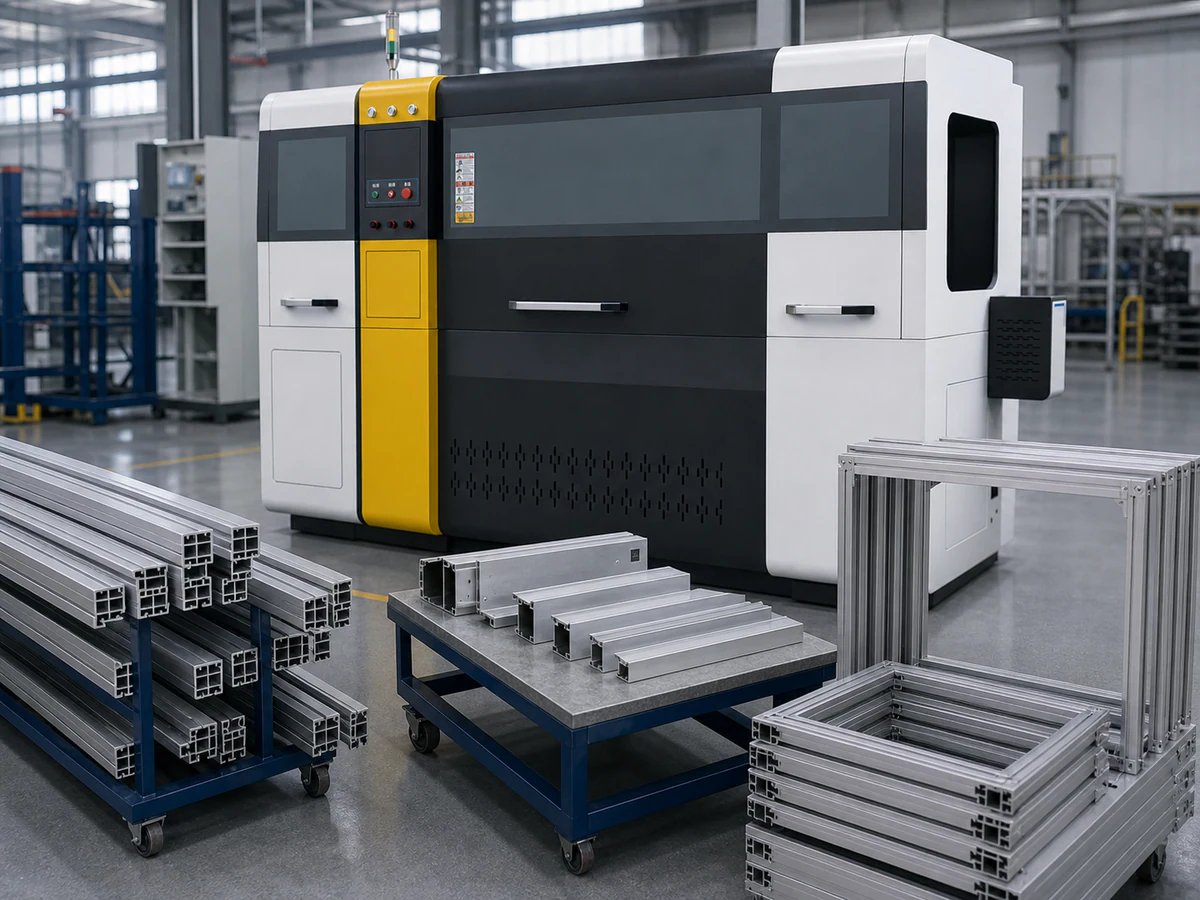
THE RISK
One efficient cut does not define an efficient frame-kit plan.
JIURUN ENGINEERING RESPONSE
Review stock, quantities, sequence, saw kerf, trims and acceptable tail against the complete cutting list.
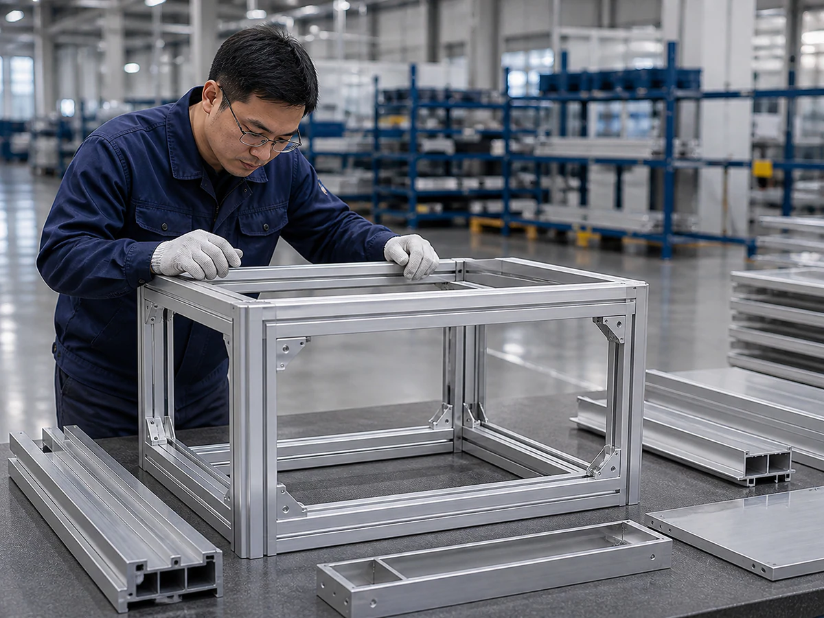
THE RISK
Marks can arise during feeding, clamping or collection.
JIURUN ENGINEERING RESPONSE
Mark critical faces and review the entire material-contact path using the agreed inspection method.
02 — BUILD THE CUTTING STRATEGY
ENGINEERING DECISION PATH
Each decision follows from the frame drawing, assembly datum and complete production list.
We start with the frame kit and its cutting requirements.
Cross-section, wall thickness, cavities and drawing revision.
Mating face, finished-length reference and inspection origin.
Stable support areas for the actual section and stock length.
Fixture contact and force direction around protected faces.
Positioning, stock support, discharge and part collection.
Finished lengths, quantities, kerf, trims and acceptable tail.
Cut face, length, repeatability, kit identification and frame fit.
Configuration and sample-check plan after the engineering review.
CUTTING STRATEGY
Recurring rails, mixed-length kits and material-use questions require different engineering checks.
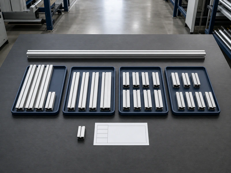
WHY THIS DIRECTIONRecurring lengths, profile support, feeding sequence and collection must be reviewed together.
Discuss Recurring Rail Batches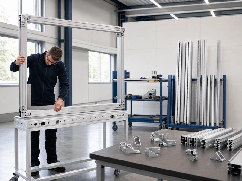
WHY THIS DIRECTIONReview the full list with part quantities and assembly references before planning changeover and delivery sequence.
Discuss Mixed-Length Kits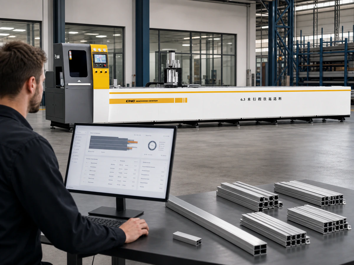
WHY THIS DIRECTIONReview realistic remaining-material assumptions. No-tail handling does not mean zero kerf or 100% material use.
Request a Material-Use ReviewMACHINE DIRECTION
Two 90° cutting platforms to discuss. Profile geometry, support, clamping and the production mix determine the final direction.
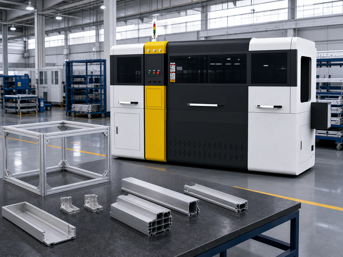
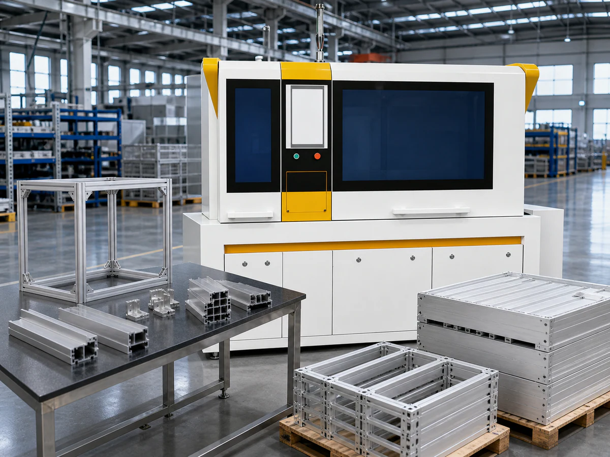
Box-type JR-650CNC-3A-1S (PDF page 8): maximum single feeding stroke 1,200 mm; separately listed maximum cutting height 230 mm and width 450 mm; 90°; brochure accuracy ±0.1 mm. JR-510CNC-3A-1S (page 9): feeding stroke 1,000 mm; height 170 mm; width 330 mm; 90°; ±0.1 mm. The same-named long-stroke JR-650CNC-3A-1S on pages 16–17 is a different configuration: feeding stroke 6,300 mm; height 230 mm; width 420 mm. Do not combine its stroke with the box-type width. Feed / discharge racks and extraction equipment are options to review, not a promise that every machine includes all accessories. Angled parts require a separate process review.
03 — VERIFY BEFORE PRODUCTION
ENGINEERING PROCESS
A practical review sequence for profile geometry, clamping, cutting and inspection.
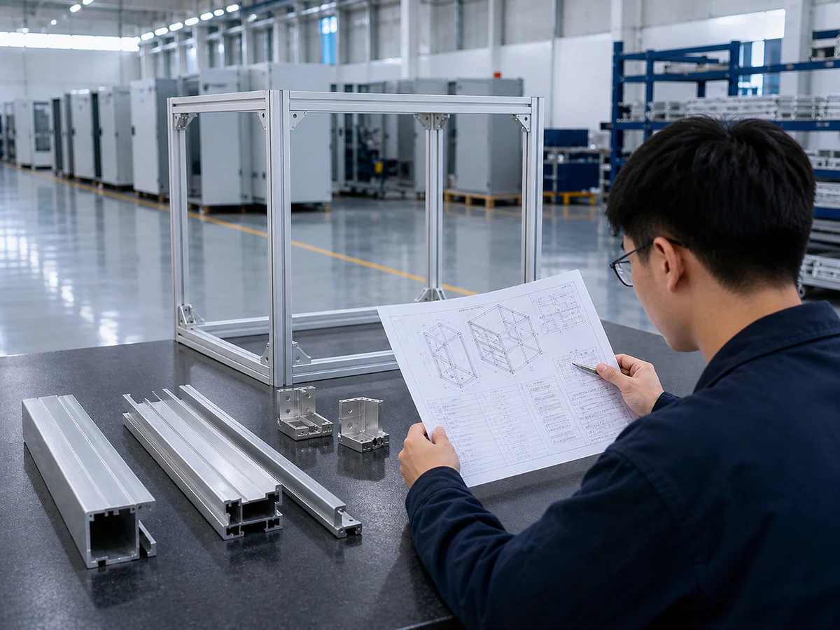
Share profile sections, frame drawings, stock lengths and the available cut list.
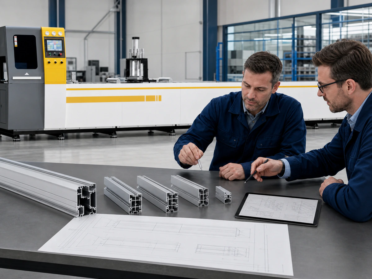
Review profile families, quantities, assembly datum and surface requirements.
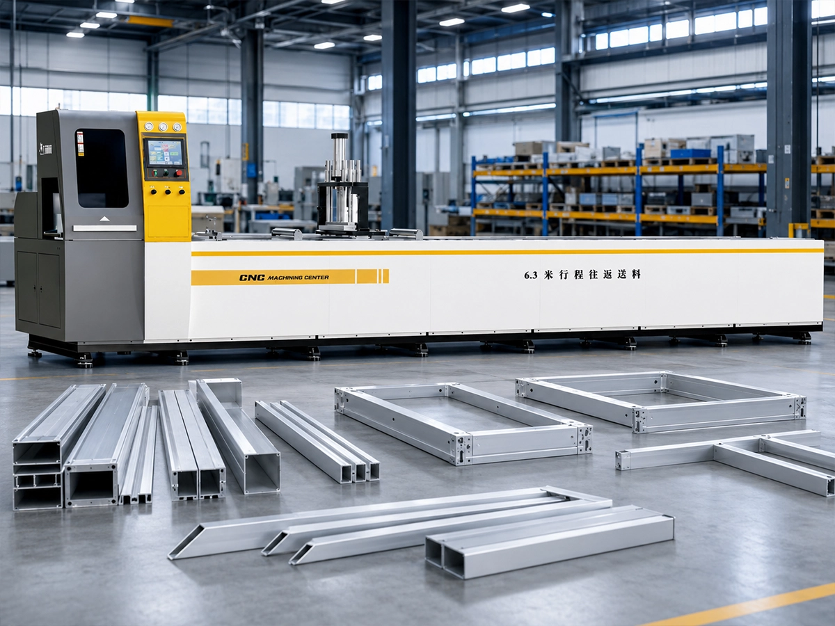
Assess feeding, support, clamping, tail handling and machine configuration.
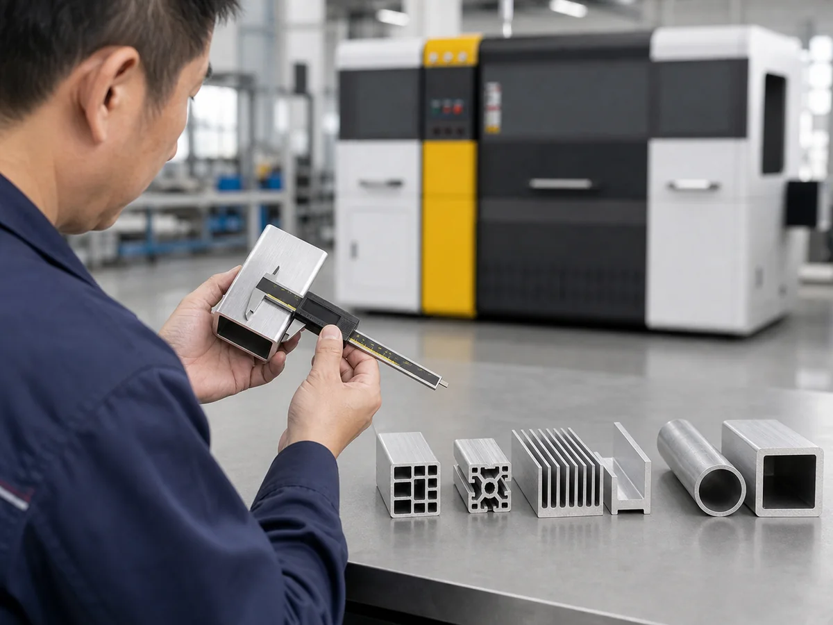
Check representative parts, finished lengths, visible surfaces and frame fit.
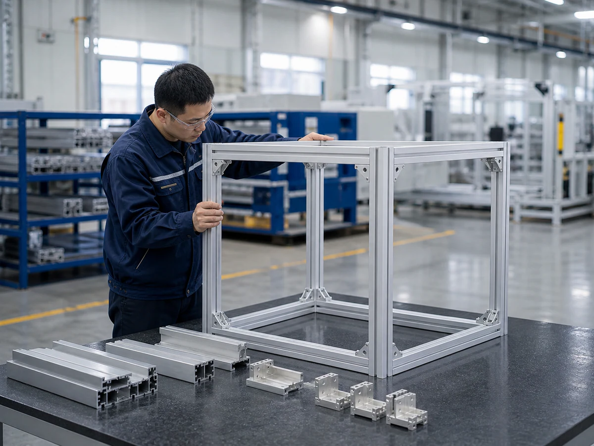
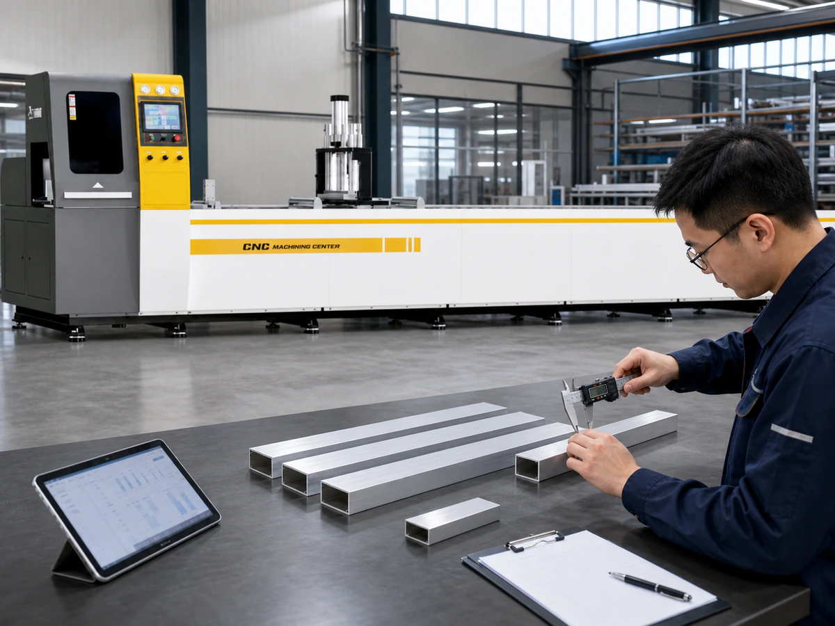
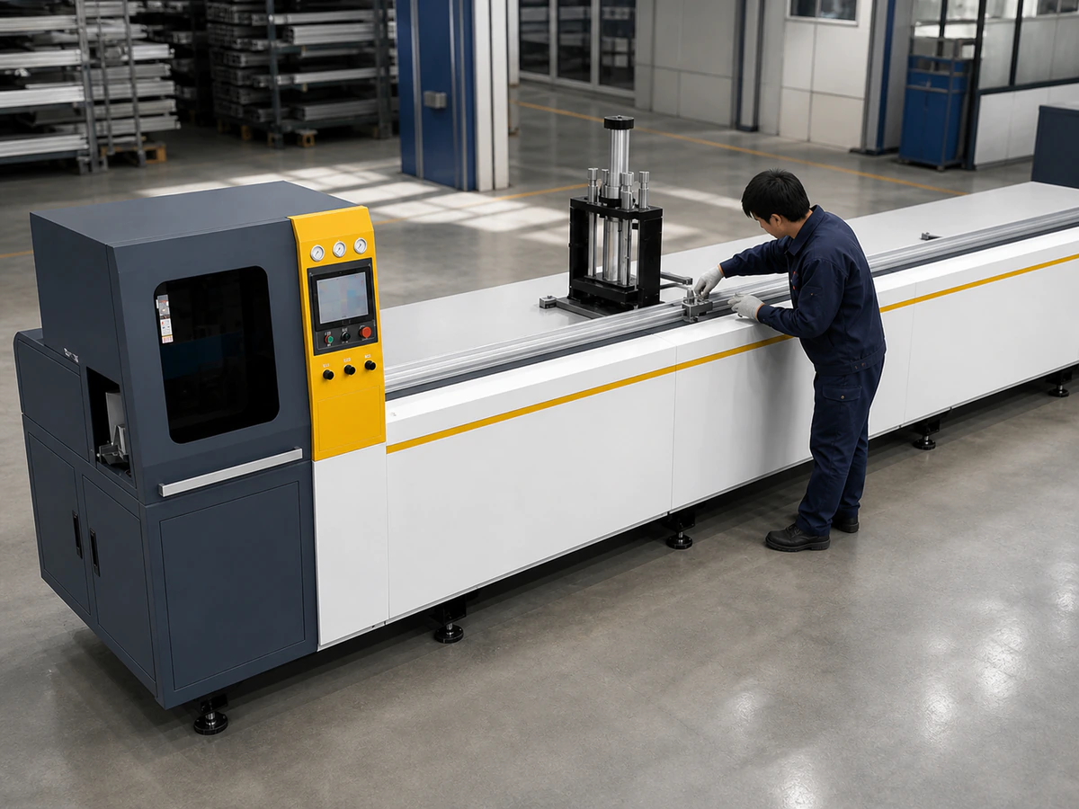
Application and engineering scenes illustrate review topics; they are not documented customer acceptance results.
PROVE BEFORE PRODUCTION
Agree on representative sections and an inspection method before sample cutting. Include important profile families and finished lengths.
A Representative Test Should Include
Inspect burrs, blade marks and visible-face condition.
Measure from the agreed assembly datum.
Check member lengths and quantities against the cut list.
Compare consecutive samples from representative sections.
Verify mating relationships and the assembled frame condition.
BEFORE SHIPMENT
FASTER ENGINEERING REVIEW
Available inputs help the team review profile support, cut sequence, material handling and sample-check criteria.
Drawing or a clear end-face photo with dimensions.
Mark the mating faces, datum and drawing revision.
Include units, available stock and required finished lengths.
List each profile ID, length and quantity; your current list is fine.
Identify inspection limits and surfaces to protect.
Share the required output, profile mix and current cutting issue.
BUYER FAQ
Direct technical answers based on the profile sections, cutting list and assembly requirement.
Send the profile cross-section for every rail or frame member, the incoming stock length, each finished length, quantities and the frame drawing that identifies assembly datums. Mark repeated jobs and mixed project batches separately. JiurunCut reviews the complete list because the best cutting sequence for one part may not be the best material plan for the whole frame. Include tolerance, visible surfaces and the current production problem so feeding, clamping, part identification and sample verification can be planned around the real project.
Possibly, but sharing one machine does not mean every profile can use the same support and fixture. Sections with different cavities, wall strength, support faces or appearance requirements may need dedicated contact parts or a planned changeover. JiurunCut groups the supplied profiles by support and clamping compatibility, then reviews finished lengths, quantities and change frequency. The final recommendation is based on the complete family and production mix; it is not confirmed from a single representative profile or a general machine specification.
The assembly datum must first be identified on the finished-part or frame drawing. JiurunCut then plans support, positioning and inspection around that mating face instead of assuming the most convenient extrusion surface is the correct reference. During sample cutting, finished length is measured from the agreed datum and representative parts can be checked against a mating component or frame fixture. This prevents a part from passing a simple overall-length check while still shifting at the connection face during frame assembly.
Mixed lengths are reviewed as a production list rather than as separate isolated cuts. The engineering review considers stock length, length sequence, quantities, repeated groups, identification and any delivery-kit requirement. A programmable or automatic direction may organize changing lengths, but fixture compatibility and material flow still depend on the real profiles. Representative production should include several important lengths and at least one realistic sequence so positioning, repeatability, remaining tail and operator handling can be checked before the final configuration is approved.
No responsible guarantee can be made from the machine model alone. Remaining material depends on stock length, saw kerf, finished lengths, quantities, cutting sequence, trim requirements and the acceptable final tail. JiurunCut can calculate and compare practical material-use directions after receiving the complete list. Where short-tail or zero-tail capability is relevant, it is evaluated against the actual stock and production conditions. The proposal should state its assumptions clearly and be confirmed through an agreed representative cutting plan. This review should be repeated when the project cut list, stock supply or acceptance assumptions change.
First mark every appearance-critical face on the profile drawing or sample. JiurunCut then reviews guide contact, support pads, clamp direction, transfer surfaces and finished-part collection around those faces. Protection cannot be judged only at the saw position because marks can occur during feeding or after the cut. Representative samples are inspected in normal light and under the customer’s agreed acceptance method. Any protective film, separator or handling requirement should be included in the project scope before fixture and collection details are finalized.
The sample plan should cover more than one clean cut. Check the cut face, burr condition, finished length from the agreed datum, repeatability across consecutive parts, visible-surface condition and the mating relationship within the frame. If the project contains several profile families or mixed lengths, include representative members from the important groups. JiurunCut records the agreed measurement method and acceptance points before testing so the customer and factory evaluate the same finished-part requirements instead of relying on a general visual impression.
The model is selected after the frame drawing, profile family, stock length, cut list, quantities, tolerance, surface requirements and output plan are reviewed. JR-650CNC-3A-1S may be a starting direction for recurring automatic batch production, while JR-510CNC-3A-1S may be considered for flexible changing lists. These are directions only. Final configuration, feeding, support, clamping and sample criteria remain subject to the real profiles and an agreed engineering review. JiurunCut therefore asks for the complete production context and confirms the decision through representative cutting before the equipment scope is released.
Send the profile sections and available cut list for engineering review.
ALUMINUM CUTTING MACHINE QUOTE
Tell us what you need to cut. We’ll confirm the details with you, recommend a machine and prepare a quote.
Prefer to chat?
Chat on WhatsAppOnly your name or company and WhatsApp / phone are required. Everything else is optional.