
A CNC aluminum saw is a useful choice when the specified job is cutting profiles to length or preparing defined end angles. A profile machining center becomes relevant when the drawing also requires operations such as drilling, routing or milling.
Some centers combine machining with sawing. Compare the actual operation list, handling sequence and inspection requirements of each quoted configuration. “CNC” describes control; it does not confirm every process your finished part needs.
Start with the finished drawing
- List every operation before comparing machines.
- Define the blank and the finished part separately.
- Ask which operations the quoted configuration completes.
On this page
1. Map the operations before choosing a CNC aluminum saw
Make a short list from the current drawing. Separate straight cuts, angled ends, holes, slots, pockets, threads and other features. Mark which features are already present in the incoming extrusion and which must be produced after it reaches your workshop.
An extrusion’s continuous groove is not automatically a machining operation. A local slot at one specified position is a different requirement. Include its drawing reference and acceptance criteria so the supplier can understand the distinction.
Manufacturer terminology also varies. Elumatec’s SBZ 151 Edition 90 description lists several profile-machining operations, including sawing. That example shows why a machining center and a saw are not always separate categories. It does not establish the scope of another machine.
For a different operation scope, Elumatec’s DG 104 description identifies a double-mitre saw with end-cutting functions. Read the operation details and control options together. A product label alone is not a completed process plan.
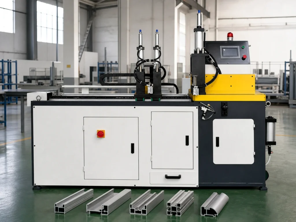
2. Define what leaves the saw
Decide whether the saw delivers a finished component or a blank for another operation. A finished component needs the specified cut faces, length, angle and other applicable drawing requirements checked before release. A blank also needs an agreed relationship to the later process.
If the next operation removes material from an end, the saw’s target length may differ from the final drawing length. The responsible process plan must define that allowance. Do not assume a universal extra length or copy a value from a different part.
Specify the cut datum, orientation and face identification. A 500 mm blank measured between one pair of faces may not match the way the finished component is located and checked. Review this relationship before the quotation becomes an order.
Use the miter cut length guide for the difference between long and short points on angled ends. Its illustrative geometry is not a machining allowance or a machine programming instruction.
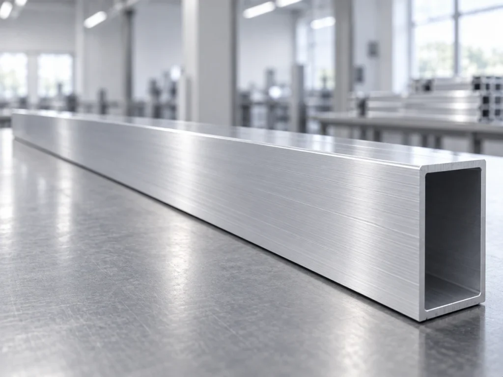
3. Review how each feature is located
Ask which drawing surfaces or features locate the workpiece at each operation. The end used to reference a hole position may be a freshly cut face, a later machined face or another specified datum. The process must preserve that relationship.
When a blank moves between machines, review how its identity and orientation remain clear. A visible mark can support part identification, but it does not establish the dimensional position of a hole. The fixture and inspection method need their own defined references.
For a machining-center quotation, identify which faces need access and which operations require a different tool, setup or fixture. The number of controlled axes does not, by itself, prove that the proposed configuration can complete every feature.
For a saw quotation, establish the required straight and angled cuts, profile support and handling. Keep any later drilling or milling explicitly assigned to its own process. Avoid leaving those operations between two suppliers’ scopes.
4. Trace the complete handling route
Draw the route from incoming stock to released parts. Include preparation, cutting, transfer, machining, inspection and packing as applicable. Identify where the part waits, who moves it and how mixed part numbers stay separate.
A single combined machine may reduce some transfers, but that does not establish the best route for every batch. A separate saw and machining station may suit a different mix. Compare the proposed sequence with representative parts and the actual production schedule.
Ask whether the quote covers stock loading, clamping, programmed operations, unloading and collection. An automatic operation in the middle does not mean that every surrounding task is automatic. Record any manual preparation and handling that remains.
The cutting cycle time guide explains why one machine cycle and the full batch period are different measures. Use the same start and finish events when comparing routes; include the downstream operations required by the drawing.
5. Specify how the part is inspected
Build the release checklist from the drawing rather than from the machine category. Cut length, cut angle, hole position and slot dimensions are separate requirements. Identify the applicable checks, methods and records for each part family.
Separate an intermediate blank check from the final part decision. A blank that passes the saw check can still require drilling and inspection. Conversely, a finished-looking component is not released until the defined requirements have been reviewed.
For a trial, ask the supplier to state which operations produced the sample and which remained outside the demonstration. Keep the sample linked to its material, drawing revision and setup. A photograph of holes or pockets does not prove the pictured saw made them.
Agree how unclear or nonconforming pieces are identified and held. A mixed collection of blanks and finished parts makes the accepted count difficult to interpret. The cut-part packaging example shows a practical way to keep release status visible during handling.
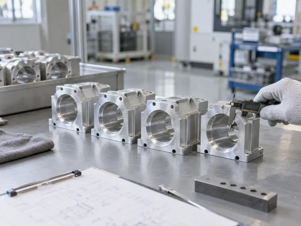
Compare two jobs with the same nominal length
Illustrative planning example: two jobs use rectangular aluminum profiles with a nominal final length of 500 mm. The numbers below explain scope only. They are not a cutting program, tolerance specification or machine-performance claim.
Job A: a cut-to-length component
Drawing scope: defined end cuts and finished length. No additional holes or local slots are required after cutting. Confirm the incoming profile, relevant surface requirements and the inspection criteria.
Quotation question: can the proposed cutting configuration produce and handle this component under the agreed requirements? Review a representative trial rather than treating “CNC” as an acceptance result.
Job B: a cut blank followed by feature machining
Drawing scope: the same nominal final length, plus two positioned holes and one local slot. The process plan must define the blank condition, feature references and any required material allowance.
Quotation question: does the offer include only blank cutting, a separate machining operation or a combined process? Identify the tools, fixtures, transfers and checks that are included. State who is responsible for any remaining work.
The equal nominal length does not make these jobs equivalent. A saw can be part of Job B’s route without completing its full drawing scope. A machining center that also saws may be another option, subject to the quoted configuration and a relevant trial.
Prepare a quotation brief that both suppliers can use
Send the current drawing, profile section, material identification, quantities and expected batch mix. Add a marked list of required operations. Describe the incoming stock and the condition you expect at the output of each proposed route.
Ask for a clear statement of included operations, exclusions and trial checks. Compare the same finished-part scope on both offers. A lower price for blank cutting cannot be directly compared with an offer that includes machining and inspection of the completed component.
For JiurunCut’s cutting range, start with the product pages and share the process brief through the contact page. Request a review of the proposed cutting stage and its interfaces with later work. Confirm model-specific capabilities in the quotation.
Common questions
Does a CNC aluminum saw automatically drill holes?
No. CNC control does not establish drilling capability. Check the operations, tools and configuration included in the offer. Any additional function needs explicit confirmation for the part and drawing being reviewed.
Can a profile machining center also cut aluminum to length?
Some configurations combine machining and sawing. Check the manufacturer’s operation list, quoted equipment and trial scope. Do not extend one center’s published capabilities to every machine described as a machining center.
Which option gives the fastest finished output?
Compare the complete route for representative parts. Include preparation, transfers, required machining, inspection and collection. A faster isolated cut does not establish a faster release of finished parts.
What should I do if the part only needs cutting today?
Define today’s confirmed requirements separately from possible future operations. Ask for clear options and their scope. Avoid paying for an assumed future process or accepting a cutting-only offer for a drawing that already requires additional features.