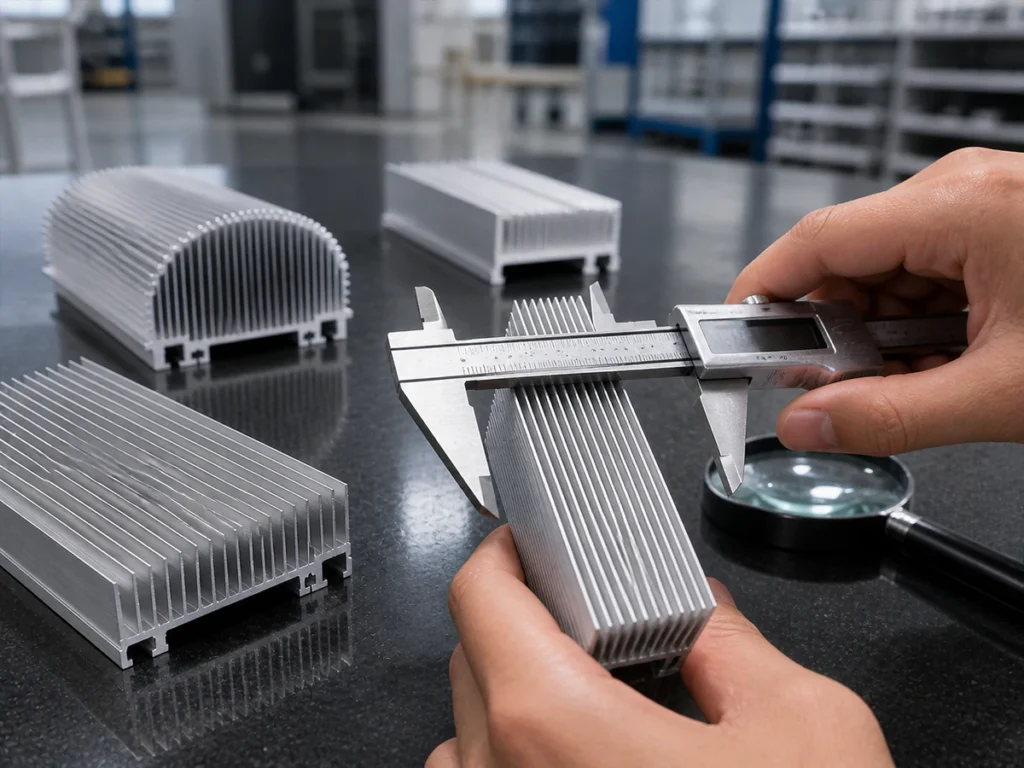
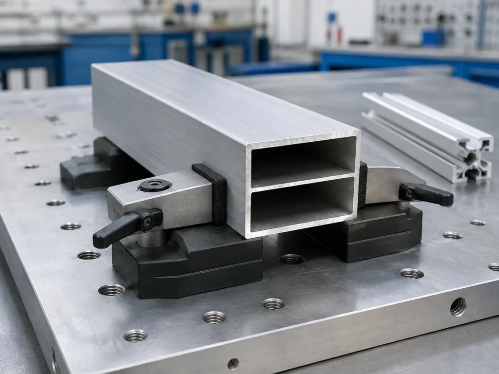
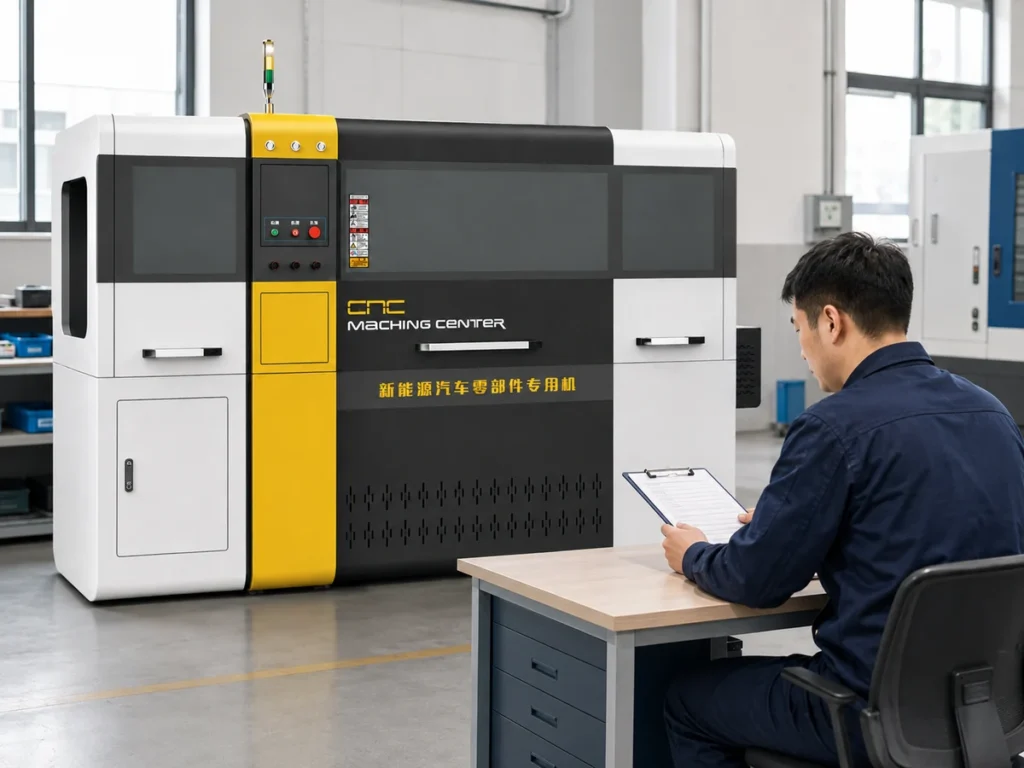
When planning cuts on a thin-fin aluminum heat sink, examine the fins, stronger base regions, holding contacts and collection path together. Outside width and height alone do not describe the job. Define the finished-part checks before choosing a setup, and inspect after normal handling as well as cutting; neither zero deformation nor a universal burr result can be assumed.
Three things to remember
- Mark the fins, base and surfaces that may or may not be contacted.
- Keep tool and holding decisions tied to the actual section.
- Check fin condition, dimensions and handling damage on representative parts.
On this page
What makes a thin-fin heat sink a different cutting review?
Its fin arrangement and base can create different support needs from a plain solid section. The locating reference, permitted contact regions and collection method therefore belong in the review alongside overall size.
The aim is an appropriate setup and sample plan for the actual profile. A photograph or general equipment label cannot establish that every heat sink will remain undeformed or meet the same edge criterion.
What should the cross-section show?
Mark fin height, spacing, base geometry and uneven features on the dimensioned section. Add material specification, finished length and a normal sample or clear photograph when available.
Identify the face used in the next operation or assembly. A datum is this specified locating or measurement reference; a convenient outside surface is not automatically the correct one.
Review difficult representative sections within the family. The strongest or shortest sample may leave the main production question unanswered.
How are locating and clamping different?
Locating establishes the part's reference position; clamping holds it there. A fixture is the support and holding arrangement that performs those tasks around the actual section.
Mark areas where fins must not be loaded or scratched, and discuss stronger base regions. “Clamp the base” is a starting question, not a complete fixture design.
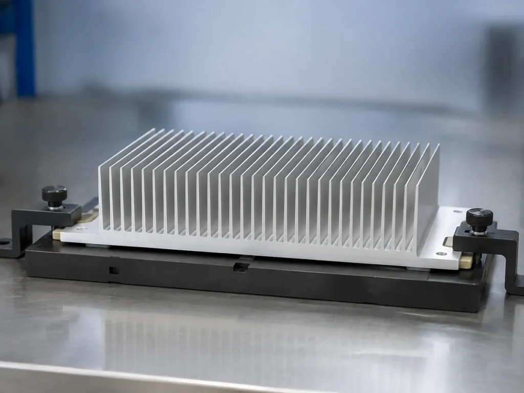
Do not infer the arrangement from another machine's photograph or invent pressure values. Setup and service belong to authorized personnel following the machine instructions; do not enter the guarded cutting zone to experiment.
What must be confirmed about the cutting tool?
“Suitable for aluminum” is not enough to approve a thin-fin job. Review the tool identity, machine configuration, profile geometry, material and acceptance requirement together.
Do not copy tooth counts, spindle speeds or feed settings from a photograph or another product's table. The approved combination matters more than a set of individually attractive numbers.
Record tooling changes and service history with the setup. That context helps explain differences between sample sequences.
Where can damage occur after the cut?
Follow the heat sink through discharge, collection, stacking and transfer. A controlled cutting result does not by itself prevent later contact damage.
Identify the first support after separation and whether fins can meet another part or a hard surface. Also decide how batches stay separated and identified.
Record if a mark first appears after collection. Keeping that observation separate from the cut-face result helps focus the investigation on the relevant stage.
What should the sample checklist include?
Agree the actual project criteria before checking samples. Tolerance means the permitted dimensional variation; where a limit matters, state its measurement method too.
| Review area | Evidence to discuss |
|---|---|
| Fin condition | Defined comparison before and after cutting and collection |
| Base / locating region | Approved datum and permitted contact zones |
| Finished length | Agreed dimension, instrument and limit |
| Cut face and edge | Specified burr and appearance condition |
| Consecutive parts | Recorded sequence rather than a single selected sample |
| Downstream fit | Representative mating or mounting relationship where required |
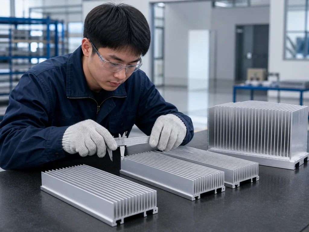
A photo of straight-looking fins is not a dimensional report. Likewise, an acceptable sample from one section does not automatically qualify the whole profile family.
Where flatness or another characteristic matters, specify how it is assessed. Displayed decimal places alone do not establish the quality of that measurement.
When should the machine configuration be chosen?
Choose the direction after defining the section, contacts, finished cut, handling and production plan. Another profile or automation requirement may need a different review.
The supplied Jiurun brochure includes JR-455Q and JR-455Y semi-automatic directions. Do not describe them as fully automatic merely because the application involves batches.
The heat-sink solution page gives application context. Use it with representative parts and requirements, not as a substitute for confirming the setup.
What evidence helps explain a heat-sink problem?
Identify material, finished length, quantity, critical surfaces and the issue. Add a whole-part photograph and a close-up of the affected feature, noting whether the condition appears immediately after sawing or after collection.
For the edge itself, read the burr investigation guide. For a broader equipment comparison, use How to Choose an Aluminum Cutting Machine.
What else should you know?
Can one fixture cover all finned profiles?
Do not assume so. Compare the actual base, orientation and permitted contact regions across the family.
Does a clean cut face prove the fins are undamaged?
No. Include fin condition and post-cut handling in the sample check.
Can Jiurun select a configuration from width and height alone?
Those dimensions help screening, but the section drawing and production requirements are still needed for a useful recommendation.
Sources & Scope
- Jiurun machinery brochure supplied by the owner. 九润画册 PDF physical pages 6–19. Machine categories and configuration identity only; not test results or an operating manual.