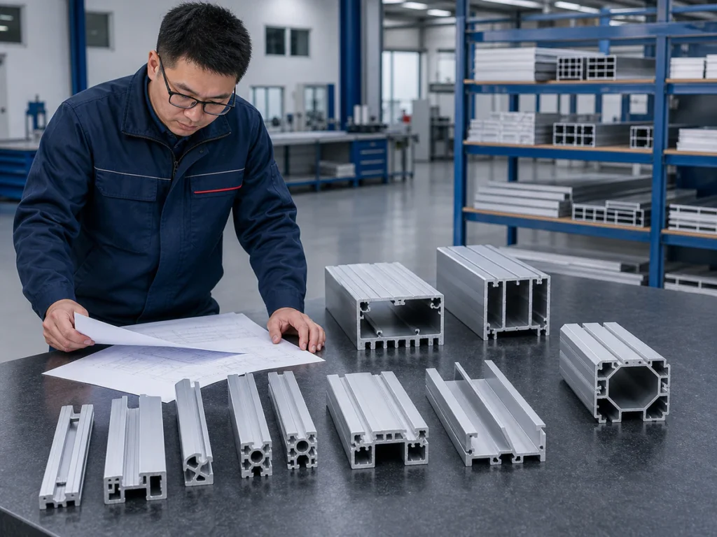
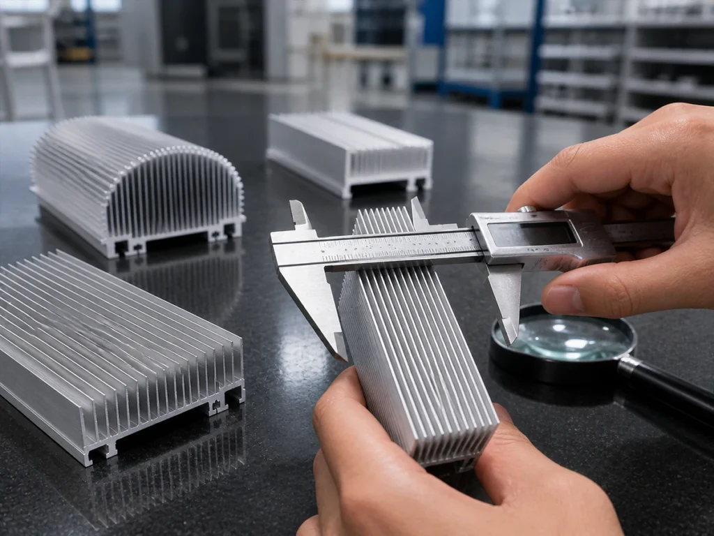
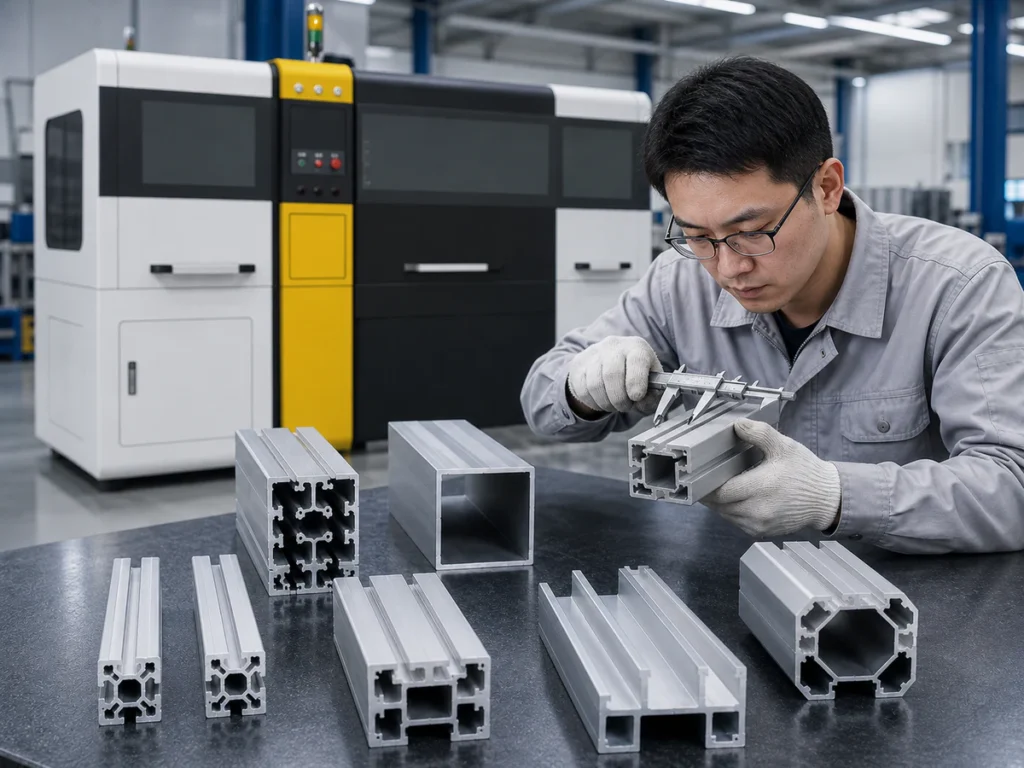
Aluminum extrusion cutting needs to produce a usable part, not just a clean-looking cut. Check how the material is supported and held, use the setup approved for the machine, and inspect the part after collection. Measure the length and angle required by the drawing, then check any surfaces or joints that matter to the next stage of your work.
Three things to remember
- Use the drawing to agree where to measure and where supports and clamps may touch.
- Check support and collection as well as the cut itself.
- Check the first and repeated parts against the same agreed limits.
On this page
What else matters in aluminum extrusion cutting?
For aluminum extrusion cutting, follow the material through support, positioning, holding, cutting, collection and inspection. A problem at any of these stages can leave you with a part that does not meet the job requirements.
This aluminum extrusion cutting guide helps production teams and buyers plan the job. It is not an instruction for adjusting or servicing the machine. Any adjustments, maintenance or access behind guards must follow that equipment’s instructions and your site’s authorized procedures.
What should you mark on the profile drawing?
Mark hollow spaces, thin walls, internal ribs, uneven shapes and faces that must remain unmarked. Also identify the datum: the reference face or edge used to locate or measure the part.
Show which edge you use to measure the finished length. The easiest face to rest on may not be the one required by the drawing or by the assembly the part fits into.
Write down any unanswered drawing questions before choosing supports. Keep a typical production sample available too. The drawing shows the intended shape; the sample helps explain how the material arrives and how you handle it.
How will the material be supported as it moves?
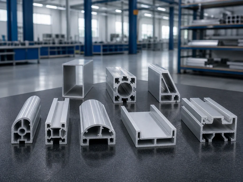
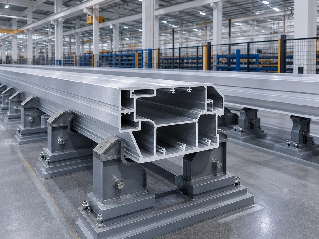
Follow the long profile as it moves towards the saw. Ask what carries it, what supports the piece when it separates, and where the finished part and remaining material go.
For long profiles, check the support before, through and after the machine together. Include the available space and equipment that feeds into the saw. Ask the supplier about the full material path; a listed feeder movement alone does not tell you which stock lengths the complete arrangement can handle.
If you plan to cut several profile shapes, compare typical examples of each. Supports that work for one shape may not suit another.
Where can the supports and clamps touch?
A fixture is the support and holding arrangement around the part. Ask which contacts position the profile and which hold it during cutting. Mark the surfaces that must not be damaged.
For an uneven shape, show which way it will sit and ask how the approved supports and clamps keep it in position. A general example cannot tell you a safe clamping force for your part.
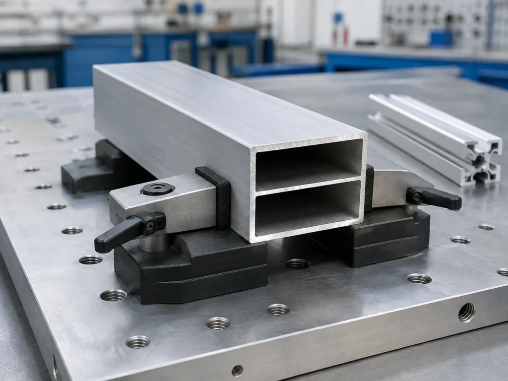
Changing a length in the program does not change the physical supports. When you switch profile shapes, different supports or clamps may still be needed, even if the program is quick to change.
Keep a setup record showing where the contacts are, which way the profile sits, which supports are used and what to check after switching jobs.
▶ Watch: Extrusion Supports & Clamps
This video shows a machine setup example. Confirm the configuration against your own profile drawing and sample.
How should the blade and cutting settings be chosen?
Check the blade and machine together. Matching the blade’s center hole and outside diameter is only part of the choice. The blade design must also be reviewed against the material, profile shape, feeding arrangement and required cut condition.
Blade makers describe the applications their tools are intended for. Check that intended use with the supplier. Do not copy one tooth shape or speed to every aluminum profile.
Use the settings and setup procedure approved for your machine. This guide does not give a universal blade speed, feeding speed, lubricant or clamping-pressure setting.
Can the part be damaged after a successful cut?
Yes. A part that looks acceptable at the saw can be marked or mixed with another job during collection and transport.
Check where each piece rests, whether it touches other parts and how different lengths are identified. If the part has visible architectural faces or thin fins, inspect it after using the collection method planned for production.
Record where a mark first appears. If it starts during collection, changing the cutting program alone will leave that part of the problem unresolved.
What should you check after aluminum extrusion cutting?
Record each result with the drawing version, material identity, profile position, supports and blade used. A tolerance is how much a size may vary and still be acceptable. Record the actual limits and how you measure the part.
| Checkpoint | What to agree before the trial |
|---|---|
| Finished length | Reference face or edge, measuring tool and allowed range |
| Cut angle or whether the end is square to its reference | How the drawing defines the angle and how you will measure it |
| Cut face | The appearance and edge condition the part must meet |
| Visible surfaces | Which faces to check and under what inspection conditions |
| Repeated parts | Which pieces to check, in what order and how to compare them |
| Assembly fit | A typical joint or part it must fit against, where relevant |
A note saying “sample passed” is only useful if it says what was checked. A photograph records appearance, but it cannot replace every size measurement.
Compare repeated pieces in the agreed order. Do not keep only the best-looking first sample as your evidence.
What should you record when the result changes?
Record any changes to the material batch, profile, program, blade, supports, collection or measuring setup. During an authorized test, change only one item at a time where the approved test permits this. That makes it easier to connect a change with its result.
Stop and tell the responsible technical team if you notice abnormal movement, suspect blade damage or have a concern about the guards. Do not keep producing parts just to collect more observations.
Keep the approved setup record with jobs you repeat. A saved program helps record the task, but it does not confirm that the supports, clamps and finished results are correct.
What information should you bring to the supplier?
Bring the profile and finished-part drawings, stock lengths, cutting list, quantities and required finish. Explain the problem you want to solve. If the saw is part of a line, show how it connects to the equipment before and after it.
Use the machine selection guide when comparing what each machine offer includes. For several profile families, the industrial aluminum profile solution provides application context.
What else should you know?
Can several sections use one machine?
Possibly. Compare all the shapes you normally cut, including how each one is supported and clamped. Fitting within the same machine capacity does not mean they can use the same supports or take the same work to switch between.
Should a sample trial use the easiest profile?
Not as the only evidence. Include the profiles and dimensions that matter in normal production. Agree which checks you will make before the trial begins.
Is a smoother-looking face enough to approve a process?
Not necessarily. You may also need the right length, angle, surface condition after handling and assembly fit. Compare the part with the drawing and the checks agreed for the job.
Sources & Scope
- Jiurun machinery brochure supplied by the owner. 九润画册 PDF physical pages 6–19. Machine categories and configuration identity only; not test results or an operating manual.
- LEUCO: NF chop saw blades for aluminum profiles. https://www.leuco.com/EN/US/Circular_Saw_Blades/NF-Circular_Saw_Blades/NF-Chop_Saw_Blades_HW-_profiles_TR-F-K-easyFix. An example of application-specific blade design and secure workholding; not a Jiurun approved blade specification.