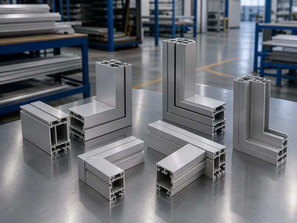
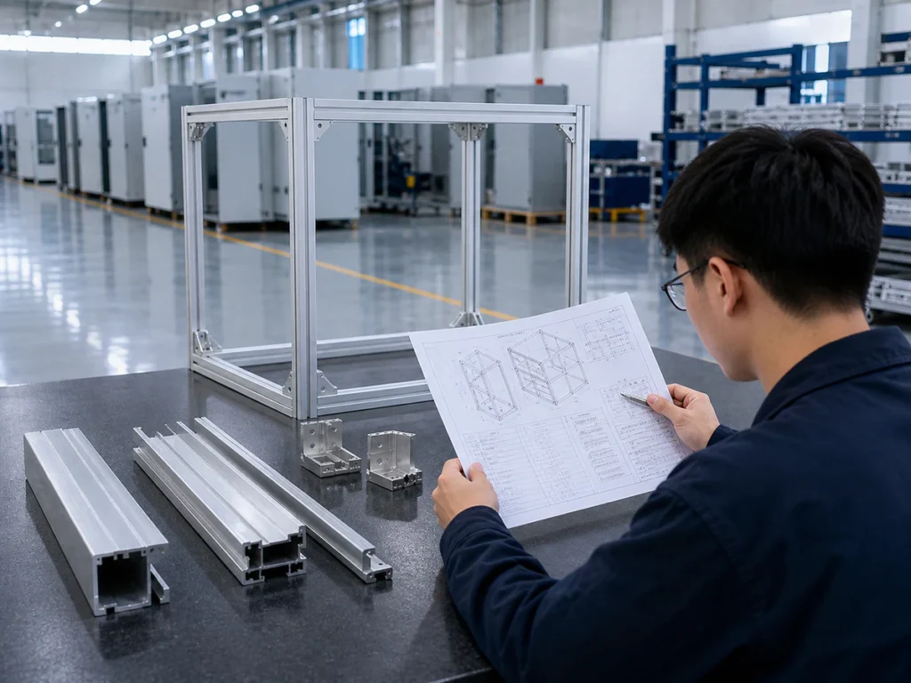
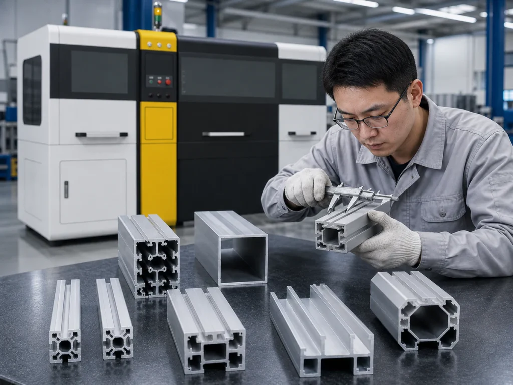
Plan each curtain-wall cut around the joint the part needs to fit. Confirm where its length is measured from, the angle, which way the profile faces and which surfaces will remain visible. Keep project batches identified and check representative joints after handling. These cutting and part checks do not certify the complete façade’s structural, fire, water or other performance.
Three things to remember
- Keep each profile and part reference with its cutting position and joint drawing.
- Protect visible faces and check them after the parts have been handled.
- Use cutting samples to check the parts; they do not certify the full façade system.
On this page
Start with the curtain-wall joint the part must fit
A cut curtain-wall profile needs to fit its intended joint and meet the required appearance. Check the profile shape, finished-part drawing, angles and visible faces together. A part can be the right length and still be wrong for the joint.
A datum is the face or edge used as a reference when positioning or measuring the part. Mark it on the drawing before comparing machine setups or inspection results.
This guide helps you prepare aluminum profiles for cutting. It does not assess or certify the structural, fire, water or other performance of the complete façade system.
Give each profile and finished part a clear identity
Identify the mullions, generally the vertical frame members, and the transoms, generally the horizontal frame members. Give them clear profile and part references, along with any pressure-plate-style profiles and special joint parts. Keep those references consistent.
Match each cross-section—the shape seen at the cut end—to its finished-part drawing. Show which way each part faces, even when two parts have the same cut length.
A photo of a glazed façade can show the type of project. It cannot replace the profile and joint drawings needed to understand the actual cuts.
Mark the faces that must stay unmarked
Mark the faces that will remain visible before discussing the fixture, the arrangement used to support and hold the profile. Show which faces matter for appearance and which face or edge is the positioning reference. Note any protective film and agreed handling requirements.
Check where the material touches supports, guides, clamps and the collection equipment. Looking only at the saw head does not cover every place where a visible face may be marked.
Agree what appearance is acceptable and how it will be inspected. “Looks good” is not a clear requirement if two teams check the parts differently.
Show length, angle and mirrored parts together
For a part with an angled end, show whether the required length is measured to the long point, the short point or another specified feature. Mark mirrored parts clearly and show how each fits into the finished joint.
The angle written on the drawing may not be the number shown on every machine display. Confirm how the drawing defines the angle and how that relates to the proposed setup.
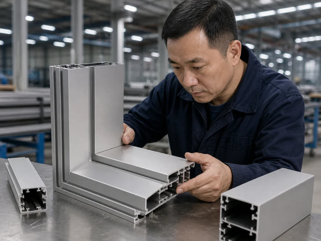
The miter cutting guide explains the difference between the angle of the joint, the angled cut face and the machine setting.
Plan how parts will stay identified in each batch
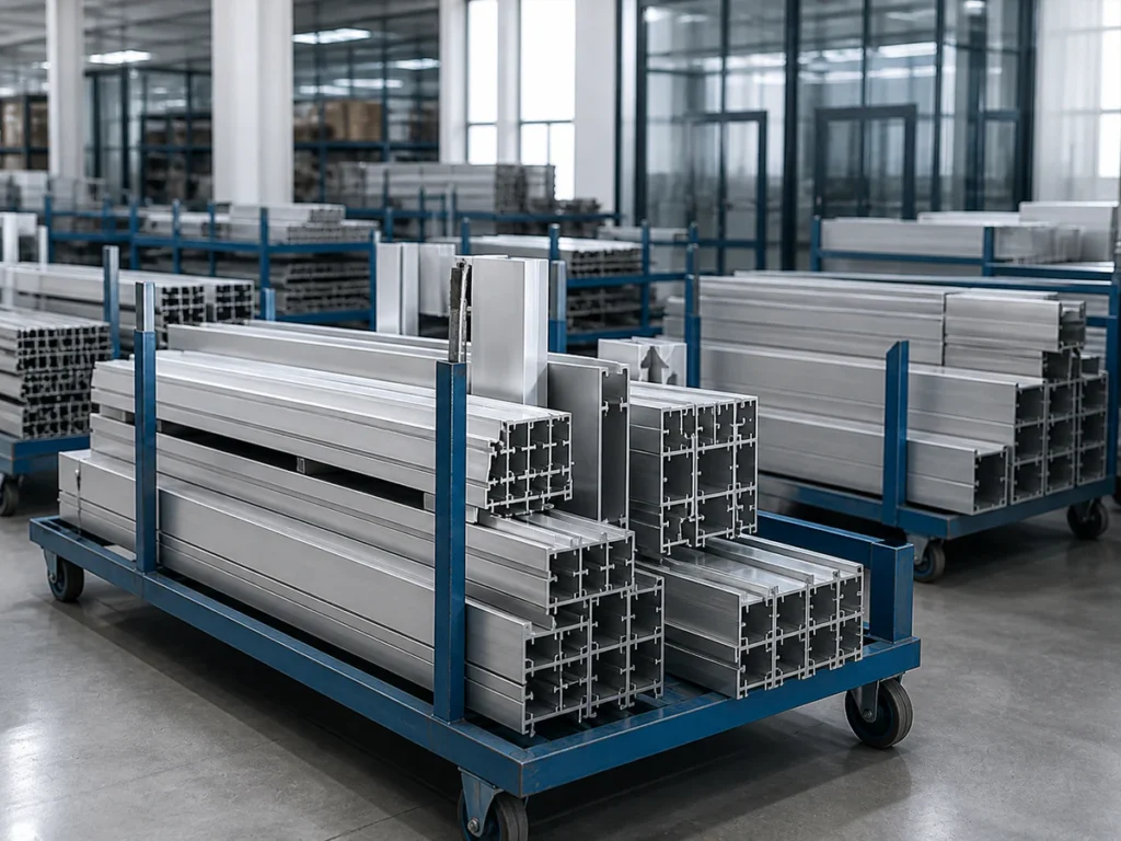
List the quantity for each part, the available stock lengths and how the next production step needs the parts grouped. One project may include several profile shapes, lengths and cutting positions.
Decide how each part will be identified after cutting. A correctly cut piece still causes a production problem if it is the wrong mirrored version or ends up in the wrong project group.
Use the current drawings when preparing the cutting list. The cut-list guide shows the information to put in each column.
▶ Watch: Positioning Profiles for Angle Cutting
This video shows a machine setup example. Confirm the configuration against your own profile drawing and sample.
Keep curtain-wall project details and sample checks together
Keep the preparation details and sample checks in the project record. Write down open questions so you do not have to recall them at every discussion with a supplier.
| Prepare for the supplier discussion | Check before approving the sample |
|---|---|
| Cut-end drawing for each type of profile | The correct drawing version and part reference |
| Finished-part and joint drawings | The agreed reference for length and method for checking the angle |
| Available stock lengths and quantities | The condition of the cut face and edges |
| Angle list and mirrored-part details | Visible faces after normal handling |
| Drawings with visible faces marked | Fit in a representative joint or assembly |
| The current production problem | Recorded results and questions still to resolve |
Use the drawing's tolerances, which state how much the finished dimensions may vary. Keep the dimension limits, cut-edge appearance and visible-surface requirements separate so each can be checked clearly.
Compare each machine using its own information
The supplied Jiurun brochure shows JR-550CNC-CORNER and JR-550Q as different angle-cutting machines. Keep their structures and listed ranges separate; information for one does not apply to the other.
Keep each machine photo with its own angle and capacity information. Ask the supplier to confirm the actual profile in the position needed for each cut.
A side-by-side comparison can help you narrow the choices. The proposal still needs to explain the supports, part handling and checks included for your job. You do not automatically need the most automated option for every project.
Check a joint that represents the actual work
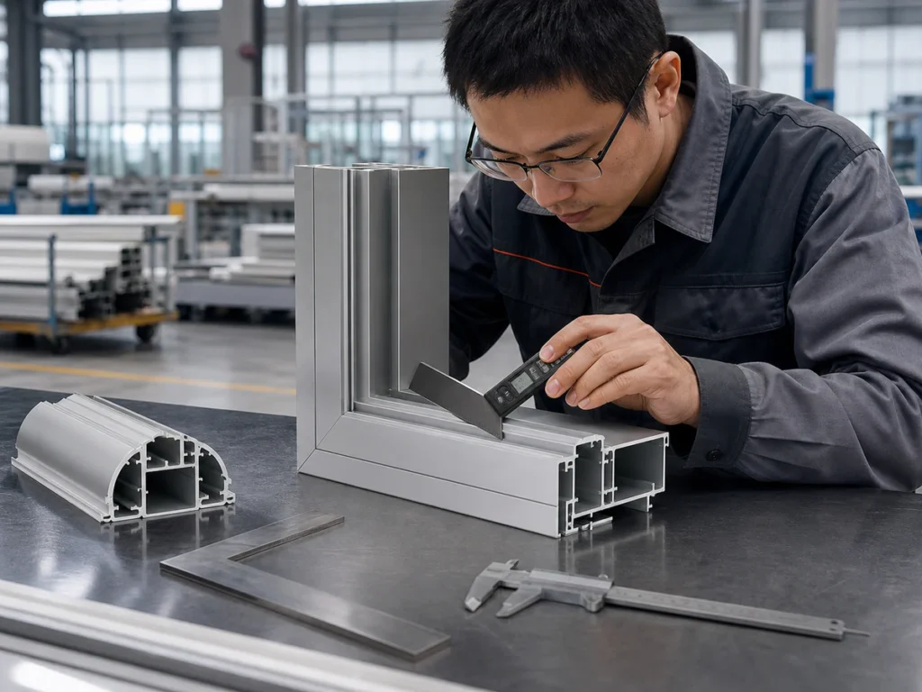
Check the finished parts and, where relevant, assemble a joint that represents the work. Use the agreed method to check the faces that meet, the seam, angle, alignment and marked visible faces.

Record which profiles and angles were tested. If the project mixes different parts, you may need more than one representative sample. Agree the sample plan for the actual job.
A successful corner sample shows only the results of the stated cutting and part checks. It does not establish the performance of the complete façade or replace the required system qualification.
Use the checklist to explain what your project needs
Bring the available profile and joint drawings, length and angle list, quantities and surface notes. Explain the production problem you want to solve, such as setup changes, damaged faces, unclear measurement references or mixed-up parts.
The curtain-wall cutting solution explains how these points fit into planning the cutting job. A clear profile or joint photo can start the discussion while the current drawings and other job documents are being prepared.
What else should you know?
Are straight lengths and angle-cut parts one review?
They can belong to one project, but state the requirements for each. Do not assume one setup will cover both straight and angled cuts.
Can a film alone guarantee surface protection?
No. Check where the profile touches other surfaces, how it is handled and the agreed result on the sample. Film alone does not provide a general guarantee.
Is a successful cutting sample a façade certification?
No. It covers only the agreed cutting and part checks. It does not demonstrate the engineering or regulatory performance of the complete façade system.
Sources & Scope
- Jiurun machinery brochure supplied by the owner. 九润画册 PDF physical pages 6–19. Machine categories and configuration identity only; not test results or an operating manual.
- Drawing reference: The Aluminum Association’s extrusion drawing publication. The linked page describes a paid drafting reference; use the drawing requirements agreed for your project.