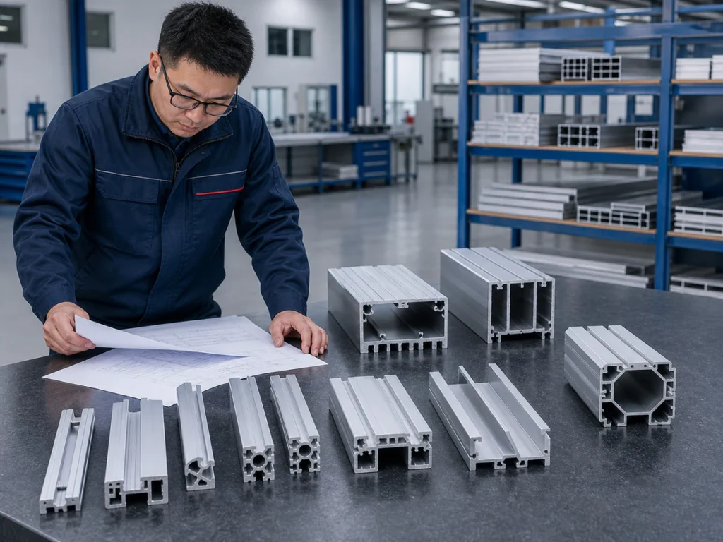
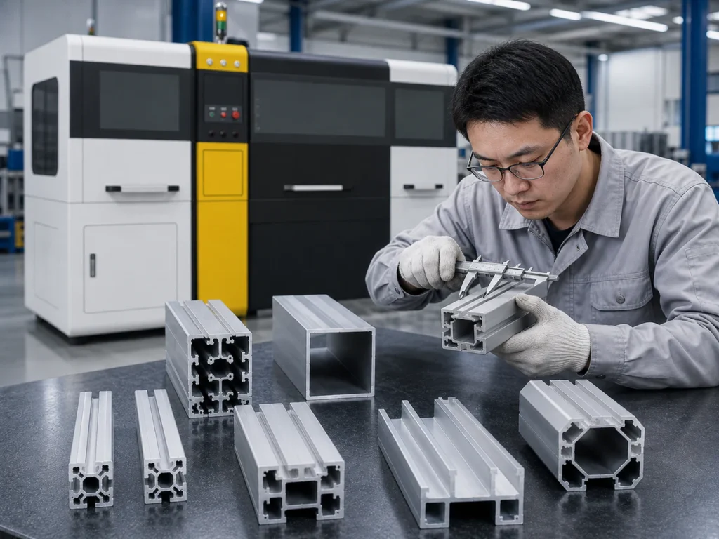
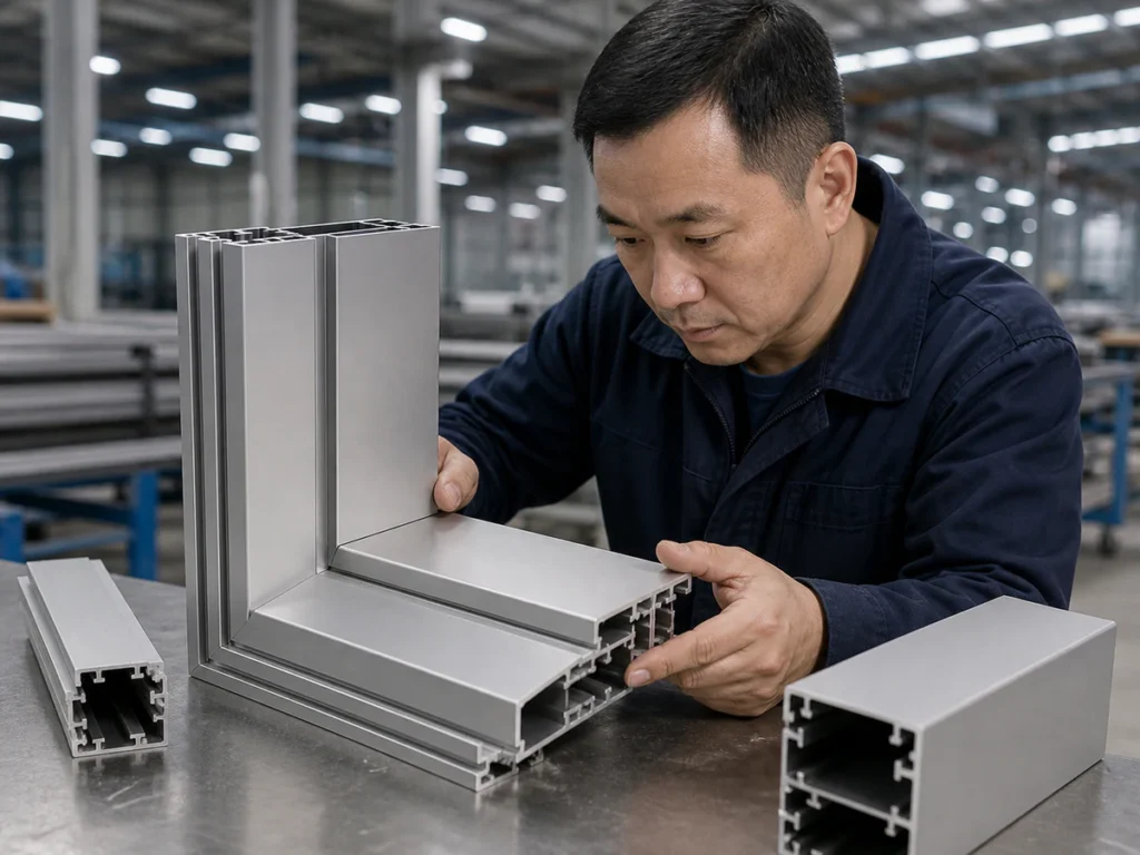
For an aluminum miter cut, show the angled joint you want to make. Mark how the angle is measured, which edge gives the finished length and which way each profile faces. Asking for a 45-degree cut is not enough: the drawing must also show the cut direction, any mirrored pieces and where to measure from.
Three things to remember
- Show the finished joint and angle reference, not just an angle number.
- Show whether the length follows the long or short edge, and identify mirrored parts.
- Measure the finished pieces and also check how a typical joint fits.
On this page
Why start an aluminum miter cut with the finished joint?
A drawing of the joint shows how the aluminum miter cut pieces need to meet. Use it to explain the cut direction, the faces that touch and which way each profile sits.
A datum is the reference face or edge used for measurement. Mark it before selecting a machine angle. This is especially useful when two similar-looking parts are mirror images.
Which four details should you show on the drawing?
Show the joint, how you measure the angle, where the length starts and ends, and which way the profile faces. Also mark any surfaces that must remain unmarked.
| Drawing item | What to make clear |
|---|---|
| Angle reference | Does the angle describe the cut face, the machine setting or the assembled joint? |
| Long-point / short-point dimension | Which edge establishes finished length |
| Mirrored parts and profile direction | Which side of an uneven profile rests against the supports and clamps |
| Faces that meet or remain visible | Which faces need to line up, and which must remain unmarked |
The long point and short point refer to the longer and shorter edges created by an angled cut. State which one your length follows, so two people do not measure different lengths on the same part.
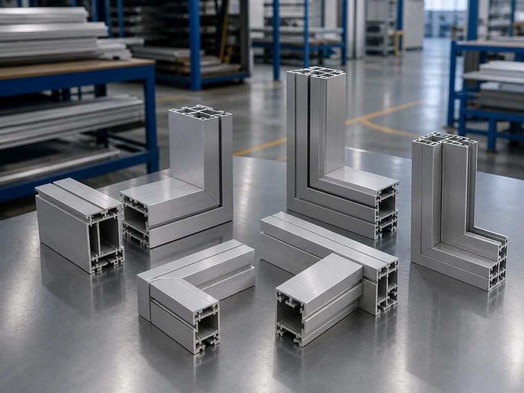
Follow the customer’s approved drawing and measurement rules. A quick sketch can help explain a question, but it must not replace the approved requirement without agreement.
Does the joint angle tell you the machine setting?
Not necessarily. In a simple symmetrical corner, the two matching cuts may share the angle equally. That does not tell you how a particular machine labels the position on its display.
For example, a symmetrical right-angle corner can be made from two matching mitered pieces. This is an illustrative example—not a JiurunCut test result or a recommended machine setting.
The supplier still needs to know which way each profile sits and where you measure its length. If the joints are uneven or use several angles, identify every part and mark the mirrored pieces. This helps keep the cut direction clear.
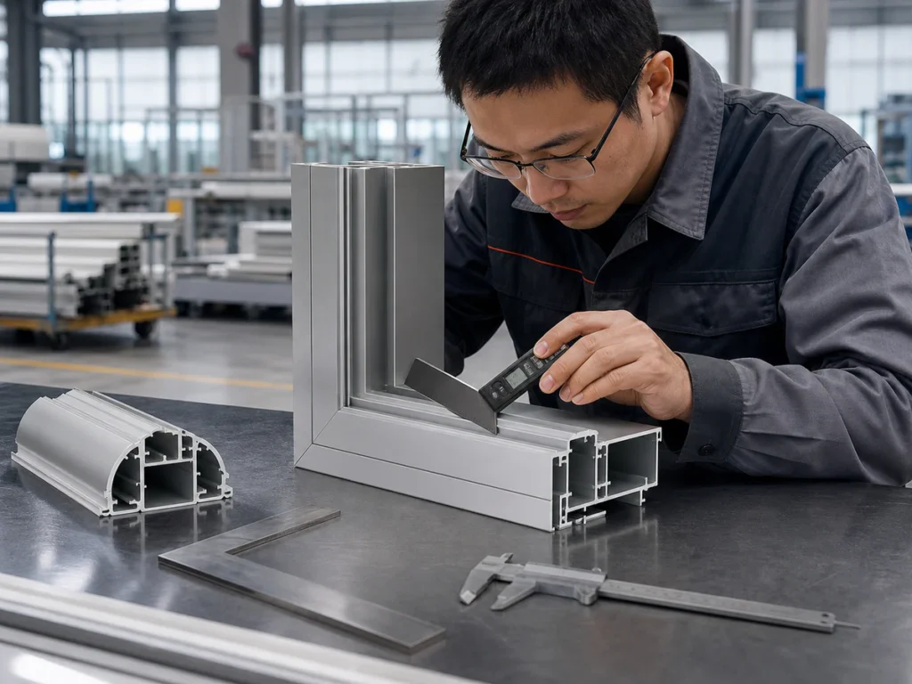
Will the profile fit at the angle you need?
Check your actual profile shape, required angle, finished length and the faces where supports and clamps may touch. A listed angle range alone does not show whether your profile fits with those supports and clamps in place.
Do not assume that a maximum cutting size quoted for one position applies at every angle. Also ask how the uncut stock will be supported and moved into place.
List the quantities and how often you change angles. Then compare repeated programmed jobs with occasional jobs that an operator loads. Neither approach is automatically the better fit for every factory.
How will you protect visible faces and keep parts identified?
A fixture is the arrangement that supports and holds the part. A face that looks best in a photograph may not be the right face to position the profile against.
Mark the visible surfaces separately from the face or edge used for measurement. Check the supports near the cut, along the material path and where the finished pieces are collected.
Decide how to keep left- and right-handed pieces identified. Even a correctly cut part can be scratched or mixed with another piece after cutting.
Any changes to supports, clamps, guards or machine settings must follow the approved setup procedure. Do not improvise clamping or expose a moving blade while investigating a joint.
▶ Watch: Positioning Profiles for Angle Cutting
This video shows a machine setup example. Confirm the configuration against your own profile drawing and sample.
What should you check on an aluminum miter cut sample?
Measure the angle and length separately. Use the agreed reference for each check and the drawing’s tolerances, the permitted dimensional variations.
If the part goes into an assembly, check a typical joint. Look at how the faces meet, how the seam lines up and how the parts locate together. This fit check adds useful information but does not replace the size checks required by the drawing.
Record which part and drawing version you checked. A photograph of one good-looking corner does not show that every angle, profile or setup will give an acceptable result.
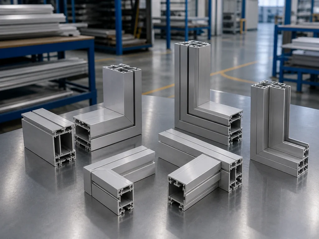
How can you compare two angle-cutting offers?
Keep each machine’s photograph, structure and specification together. The supplied Jiurun brochure shows different angle-cutting arrangements. Each arrangement has its own stated capacity and angle range.
Do not combine an angle range from one table with a feeding arrangement from another machine. Ask the supplier to identify the exact equipment in the quotation and the current specification that goes with it.
The corner-cutting equipment range can help you see which types of machine to compare. You still need to check your actual joint and required angles.
What should you send to the supplier?
Send the profile, finished-part and joint drawings, along with the angles, quantities, stock lengths and measurement method. Mark visible faces, places where supports and clamps may touch, and any mirrored pieces.
For architectural projects, continue to the curtain-wall cutting solution. For the rest of the purchasing comparison, use the machine selection guide.
What else should you know?
Does a programmed angle prove the finished angle is acceptable?
No. Measure the finished part from the agreed reference, using the agreed method. The programmed position alone does not show that the finished angle meets the drawing.
Can a straight-cutting configuration be assumed to handle miters?
No. Ask which angled cuts the machine is designed for, how it will support and clamp your profile, and whether there is enough usable space for the part.
Should all parts use the same length reference?
Use the reference specified for each part on its approved drawing. Make sure the drawing, machine setup and inspection all use that same reference.
Sources & Scope
- Jiurun machinery brochure supplied by the owner. 九润画册 PDF physical pages 6–19. Machine categories and configuration identity only; not test results or an operating manual.
- Drawing reference: The Aluminum Association’s extrusion drawing publication. The linked page describes a paid drafting reference; use the drawing requirements agreed for your project.