
The pusher completed its stroke, but the aluminum bar barely moved. That observation can turn one programmed length into a short part, a missed cut, or a stopped cycle. It does not yet identify a faulty servo or a weak clamp. A position display normally tells you where an axis went; it cannot, by itself, prove where the stock went. For an aluminum saw pusher stock slip investigation, keep those two movements separate.
The feed arrangement matters. Some machines press on the rear end of a bar, others carry it with a gripper, and others cycle a local clamp. Ask which arrangement is actually in the quoted machine before applying any of the checks below. The examples are a diagnostic method, not a claim about a particular Jiurun model or installation.
Measure the gap between axis travel and stock travel
Begin with the machine stopped and made safe under its operating procedure. Record the program length, the displayed feed-axis start and end positions, and the bar’s position against a fixed, visible reference. Put any witness mark on the stock only while the equipment is stopped. During a controlled cycle, observe from outside the guarded area; do not reach toward a moving pusher or open a guard to watch it.
If the axis moves the requested distance and the stock does not, the loss lies between the moving feed element and the bar, or in resistance along the stock path. If both axis and stock stop early, investigate the commanded stroke, limit, alarm or reference first.
If the bar follows at first and then falls behind, note when that happens: at acceleration, on a particular support, near the final remnant, or during a return and regrip. Those patterns lead to different questions.
Use one identifiable profile, one orientation and one program for the first comparison. Record the bar end and the same fixed reference before and after each feed. A finished part length alone mixes feed behavior with blade position, kerf, datum and cutting effects. For a separate reversal-length question, see our feed-reversal check.
Aluminum saw pusher: find the contact carrying the bar
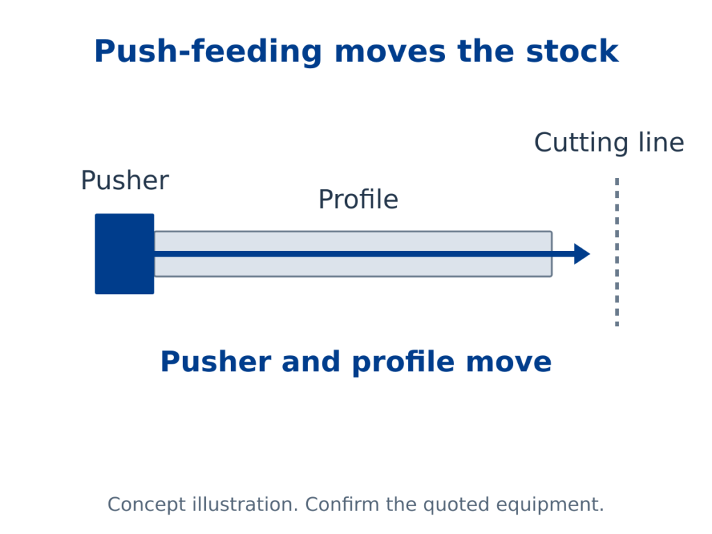
On an end-push system, the pusher face must actually meet the intended end of the bar without riding past, under or above it. A profile may be missing, rotated, bent at the end, or sitting at a different height than the pusher contact. A gap at the beginning of a stroke can look like slip even when the drive works normally. Record the contact position before changing any stop or software limit.
On a gripper-fed system, check the specified jaw faces, closure sequence and the profile surfaces they touch. A gripper can close and its carriage can travel while the profile shifts inside the jaws. Contact area, jaw condition, available gripping force, profile geometry and acceleration all matter.
Elumatec’s pusher-saw catalog explicitly separates the pusher carriage from its pneumatic gripper jaw and says the jaws, support blocks and clamps need adjustment for different profiles. This is an example of a machine design, not evidence that the Jiurun saw being considered has those components. Festo’s gripper data likewise shows that the lateral force before a workpiece slips depends on the stated gripping conditions; its numbers should not be transferred to a saw without a matching test.
On a cycling-clamp or roller-feed design, identify the element that moves the stock on the forward stroke and the element that must release or support it. If an infeed roller appears stationary, first confirm whether the profile is touching it; our roller-contact guide covers that different symptom. Do not label every short feed a gripper problem.
Check resistance without sacrificing the visible surface
A bar may move freely for most of its length and then bind at a guide, support transition or cutting-station entrance. Look for a repeatable point where the leading end pauses, a support loses contact, or the profile rotates. Compare the same bar with its normal protective film and without any unapproved alteration.
Note scratches, pressure marks and deformation along with feed distance. Increasing grip pressure or acceleration to make the motion pass can hide a setup problem while damaging a thin wall or a finished face.
The feed supports and the holding interface must be reviewed together. Emmegi’s bar-feeder description identifies a gripper and carriage drive as separate functions; its loading description also distinguishes profiles that remain stable during transport from those that do not. That supports asking for a profile-specific transport trial, not assuming that a generic feed specification covers your section.

Make the next trial answer one question at a time
Agree a small observation sheet with the supplier or maintenance team before the trial. For each run, record the actual profile drawing or sample identifier, orientation, bar length, surface condition, feed method, commanded travel, measured stock travel and any new marks. Keep the guard and operating procedure intact. If the result changes, vary one condition at a time rather than changing grip, support and speed together.
- First full bar: Does contact occur before motion, and does the bar follow the first feed?
- Repeated feeds: Does a gap accumulate between carriage travel and bar travel, or appear only after regrip?
- Short remnant: Is the remaining length still within the proposed feed mechanism’s supported and grippable range?
- Alternate section: Does a different wall, cavity or contact face require a different jaw or support setting?
These are proposed observations, not acceptance tolerances. Write the acceptable stock-travel difference, visible-surface condition and permitted short-part range into the purchase specification or service record for the actual build. Do not use a catalog’s positioning figure as a substitute for a witnessed stock-travel measurement.
Ask for a feed-path answer, not a drive-only answer
When requesting a remedy or quotation, send the supplier the profile drawing, actual sample and photographs of the loading orientation, feed contact and support transitions. State whether the machine pushes, grips or cycles a clamp; if that is unknown, ask the supplier to identify it in the proposed configuration.
Request a short video or witnessed run that shows both the feed element and a fixed stock reference through the same cycle. Ask who sets jaw/contact parts, how a changeover is recorded, and what happens at the shortest approved remnant.
This discussion is narrower than feed-carriage homing after power loss: an axis can have a valid reference and still fail to carry the bar. It is also distinct from choosing the general incoming-stock envelope. Here the decision is whether the actual contact-and-support arrangement transfers a commanded movement to your profile without unacceptable marks.
Related equipment video
The following video is from the JiurunMachinery channel and shows another automatic aluminum cutting machine with a long feed layout. It is equipment context only. It does not document the bar, grip design, fault, sample, settings or trial result discussed here.
Send the profile and the two travel measurements
If your pusher moves while the aluminum bar stays put, contact JiurunCut with the profile drawing or sample, feed layout, commanded-axis travel, observed stock travel and the point in the cycle where they separate. Ask for a configuration-specific contact and support review, followed by an agreed witnessed trial. That gives both sides a concrete answer before a feed feature is promised or a machine setting is changed.
Sources used for general equipment principles: Elumatec aluminum-industry saw catalog; Emmegi bar-feeder overview; Festo gripper datasheet. The cited products and figures are not Jiurun configuration claims.