
Aluminum angle cutting needs a section drawing and an oriented part view. Identify both legs, thickness, material condition, cut length and end geometry. For a mitered or later-drilled part, show which face is the reference and which way the section faces. A length and the word “angle” leave too much open to interpretation.
This guide covers the purchasing information for an L-shaped section. Keep the section’s corner angle separate from the angle of the cut across its length.
Three details that prevent an incomplete quote
- Name the section and both leg dimensions.
- Show orientation, ends and the length reference.
- Define the accepted part and any later operations.
On this page
1. Identify the section for aluminum angle cutting
Start with the profile drawing or controlled stock specification. State both leg dimensions, thickness, material identity and incoming length. Include the specified corner shape and any additional features that distinguish the actual section.
An equal-leg section and an unequal-leg section should have separate identities in the request. One photograph of an L-shaped piece does not establish either leg dimension, thickness or material condition.
Online Metals’ angle listings distinguish equal and unequal legs and present leg sizes separately from thickness. That product structure illustrates the information needed to identify the stock. It does not establish a suitable alloy or cutting setup for your component.
Hydro’s UK standards catalogue also separates equal and unequal angles into different groups. Use the drawing for the actual selected section rather than treating all angle profiles as interchangeable.
Retain the alloy, temper and finish requirements from your material specification. Do not identify them by color or by comparing the photograph with a catalogue image. If a proposed substitute is being considered, obtain the responsible approval before changing the stock identity.
Our 6061 and 6063 cutting guide explains why the material condition belongs in the job description. Neither a familiar alloy name nor a nominal profile size confirms the complete material requirement.
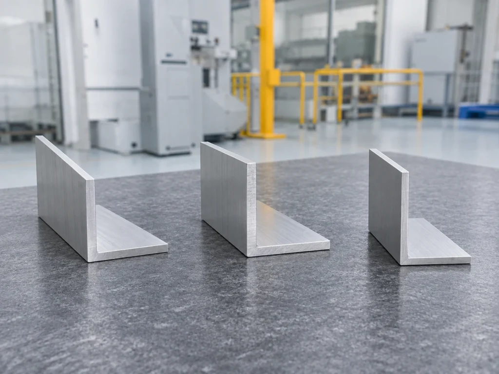
2. Show the orientation in an end view
Provide an end view that makes the two legs easy to identify. For an unequal section, label the legs or their reference faces consistently with the part drawing. Use those same labels in the cut list and sample-review information.
A view marked only “50 by 30” can leave the intended presentation unclear. The dimensions identify the nominal legs, while the oriented view explains which leg is shown at the top, side or other reference position in the part drawing.
Ask the machine supplier to review the actual section and proposed presentation. The review should address the compatible support, clamping and handling arrangement. A generic capacity rectangle or a large enough blade diameter does not confirm that complete arrangement.
Keep this as an engineering review request. The purchasing drawing is not permission to improvise supports, change guards or operate the section in an unapproved position. Use the instructions for the actual machine configuration.
If several sections appear in one quotation, identify which arrangement applies to each. Ask whether a different section requires supplied tooling, a planned changeover or a separate configuration review. Record what the quotation includes.
For the broader distinction between size limits and a reviewed application, see our cutting-capacity diagram guide. Keep the actual profile outline with the request.
3. Define the ends and the length reference
Show each end separately. A square end and a mitered end require different drawing information. For a miter, include a view that identifies the cutting plane and the reference used for the stated angle.
The corner between the two legs belongs to the cross-section. The miter belongs to the end geometry along the piece. Calling the material “90-degree angle” does not specify that both ends are square to its length.
State where the required length is measured. On a sloped end, points on different faces can have different distances to the opposite end. An overall dimension without a clear extension line can therefore be interpreted differently by two suppliers.
Our miter-length guide explains the difference between long and short reference lengths using ideal geometry. Apply the approved drawing to your actual section rather than borrowing a result from another profile or cutting plane.
An invented drawing comparison
Imagine a hypothetical 50 by 30 mm L-section with a 400 mm required length. One drawing shows two square ends. Another shows a miter at one end and dimensions 400 mm along a named reference edge.
Both records contain “400 mm,” but they describe different geometry. The values are invented to explain the information gap; they are not stock dimensions, machine ratings or a recommendation for a particular part.
Keep blade loss, trimming and stock planning separate from the required part length. A finished dimension should not silently include a supplier’s assumed allowance or an adjustment made for the cutting process.
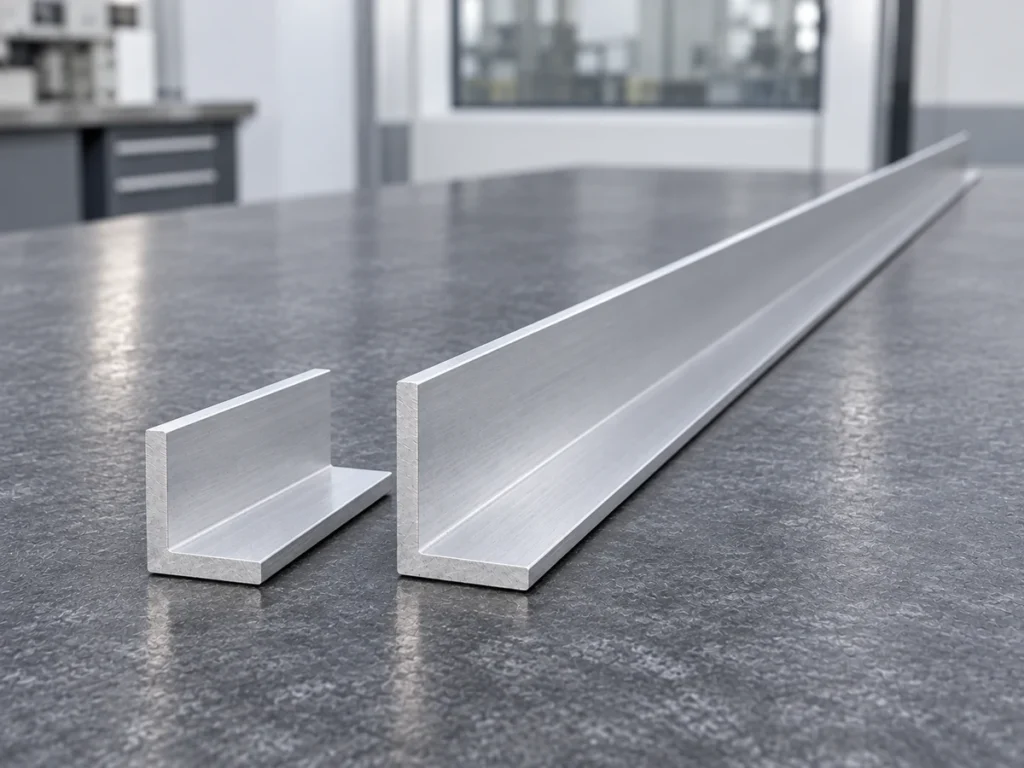
4. Separate matching pieces from mirrored parts
If the assembly needs left and right parts, give each its own identity. Show the oriented views and quantities in the drawing package. Do not rely on a note saying “make a pair” when end geometry or later features differ.
Two pieces can share the same section and length yet have different end directions or hole locations. Conversely, turning an otherwise identical square-cut blank may be enough for a particular assembly. Let the controlled drawing establish which situation applies.
A parts list should distinguish the cut blank from any later drilling, notching or machining. If left and right identities arise only in a later operation, make that handoff explicit. The saw quotation should state the stage it supplies.
For a hypothetical order of 12 assemblies requiring one left and one right component each, the complete component requirement is 24 pieces. If one right component is held for review, 12 left and 11 right components provide 11 complete pairs, with one left component unmatched.
These quantities explain kit completeness. They do not describe an actual production result or imply that a held component is rejected. Keep its status and disposition visible rather than counting it as ready for assembly.
Connect any drawing change to the affected part identity and quantity. Our cut-list revision guide explains how to preserve that connection when earlier pieces already exist.
5. Review the actual sample against the named features
Prepare the sample-review requirements before comparing machines. Include the features the cutting stage must supply: section identity, length reference, end geometry and specified condition of the relevant surfaces and edges.
Review both legs where the drawing requires it. A satisfactory dimension on one visible face does not automatically establish every required feature on the other leg. Keep the inspection method and reference consistent with the agreed requirement.
Have the responsible team define how incoming section condition and cutting results are distinguished. A visibly uneven leg or a surface mark should be recorded with its location and stage, rather than immediately assigned to the saw.
If the piece will be drilled or assembled later, identify which later checks are included in the review. A cut blank that meets its agreed requirements has not automatically passed the final assembly or load requirements.
Record the material, tooling and configuration used for the sample. Keep the observed results tied to the agreed cases. Our inspection-sampling guide explains why a few reviewed pieces do not establish acceptance of an entire future lot.
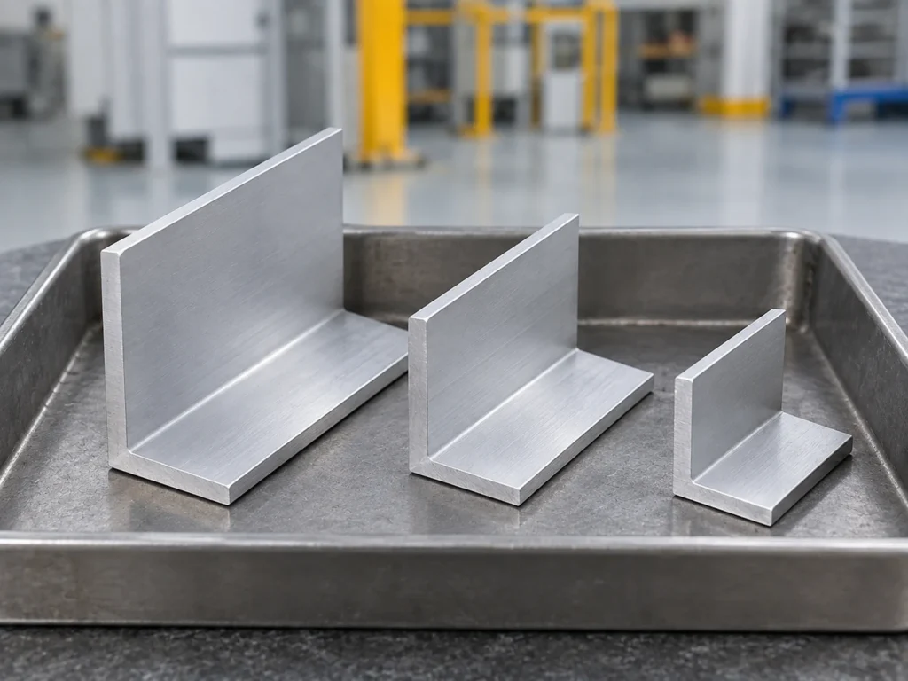
6. Make the aluminum angle cutting quote easy to compare
Send the same controlled drawing package and quantity basis to each supplier. Ask for a proposal that identifies the reviewed sections, cut geometries, handling arrangement and included equipment.
Cutting scope: state which ends and lengths the proposal supplies, and whether the output is a blank or an assembly-ready component.
Changeover scope: identify the supplied arrangements for the different sections and orientations in the job list. Clarify what is included in the handover.
Later work: list drilling, notching, deburring or machining separately when required. Do not assume those operations are included because an illustration shows a finished bracket.
Acceptance: retain the approved features, review method and quantity basis. Compare evidence for those same requirements before comparing cost per piece.
This makes a smaller proposal easier to assess alongside a more automated one. The useful comparison is the documented job and accepted output, with equipment and responsibilities clearly identified.
Common questions
Does the nominal leg size confirm that an angle will fit a saw?
No. The supplier needs the actual section, presentation and required cut geometry to review the complete handling and cutting arrangement.
Are all 400 mm angle pieces the same cutting job?
No. Square and mitered ends, length references and orientation can describe different parts even when the stated length is the same.
Can one blank represent both left and right components?
Sometimes, depending on the controlled drawing and later operations. Identify the supplied stage and keep any differing component identities visible.
Review your angle-section drawing with JiurunCut
Send the section and oriented part views, required quantities and end requirements. Ask us to review the proposed cutting arrangement and define what the quotation supplies.