
Heat sink thermal resistance is useful only when the heat-flow path and operating conditions are clear. Before comparing aluminum heat sink quotations, identify the measured temperatures, heat load, airflow, part geometry and mounting arrangement.
A smaller catalog number may look attractive. First check whether both numbers describe the same task. A value for one mounting position or forced-air condition should not silently become the requirement for a different assembly.
On this page
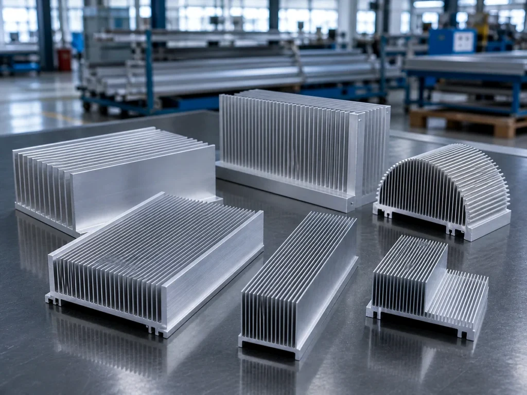
What the thermal resistance describes
Boyd’s board-level heat sink catalog separates junction-to-case, case-to-mounting-surface and mounting-surface-to-ambient thermal paths. Its heat sink selection section identifies each path and the corresponding temperatures.
That distinction belongs in the RFQ. Ask whether a quoted value concerns the heat sink alone or a larger path through the device and interface. Preserve the supplier’s definition and units with the number.
Material thermal conductivity and a heat sink’s thermal resistance are also different inputs. Use the aluminum thermal conductivity guide to organize material data; request the actual heat sink performance basis separately.
For procurement, the useful question is simple: does the proposed component satisfy the requirement in the assembly you plan to build? Give the thermal designer the agreed conditions and ask for a documented selection against them.
Five inputs for the RFQ
1. Heat source and required temperature
Identify the device or heat source, its contact footprint and the heat load the designer should evaluate. State where the allowable temperature applies: a device junction, case, mounting surface or another defined location.
Have the responsible engineer approve those inputs. An undefined “maximum temperature” can cause suppliers to compare different points in the heat-flow path.
2. Ambient and cooling arrangement
Describe whether the assembly uses natural convection or forced air. Identify the ambient reference and provide the airflow information used for the proposed selection.
Ask the supplier to show the airflow basis at the heat sink. A fan’s product label is not a complete description of the assembled cooling arrangement.
3. Exact heat sink geometry
Supply the section drawing, length, base dimensions and intended mounting position. Keep the geometry revision connected to the thermal proposal.
Catalog definitions may have a specific length basis. For example, Wakefield Thermal’s 127712 listing labels a thermal field with a three-inch basis while also listing a different overall product length. Ask the manufacturer how the field applies to the selected finished component; do not rescale it by guesswork.
4. Mounting and interface
State the mating surfaces, attachment arrangement and proposed interface material. Ask the designer to identify the relevant mechanical and electrical requirements with the thermal ones.
Boyd explains that interface materials address microscopic gaps and surface irregularities between solid surfaces. Review the selected interface in its installed condition rather than treating an aluminum base as the complete thermal path.
The thermal pad versus paste guide helps organize that separate interface review.
5. Finish and delivered condition
Identify the actual finish, machined regions and mounting-face requirements. Ask whether the performance information applies to that delivered condition.
Keep any requested coating or machining change visible to the thermal owner before approving a substitute. A part that fits mechanically still needs to match the agreed thermal review.
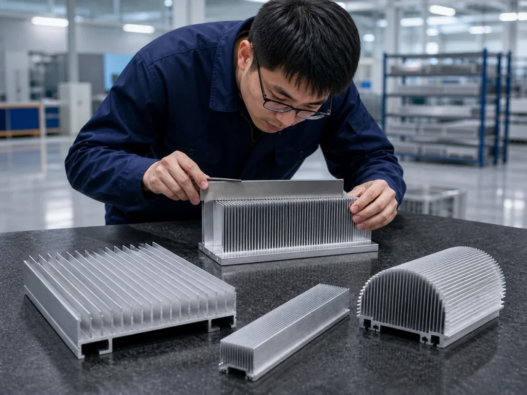
Read the right performance curve
Boyd’s graph-reading guidance distinguishes natural-convection plots from forced-convection plots. It also states that the catalog graphs assume proper device mounting and the recommended heat sink position.
Check the axes and the curve description before taking a value into your comparison. Retain the stated heat load or air velocity and the temperature reference with the result.
Have the supplier identify the exact part and graph used. If a quotation offers a single number without its conditions, request the supporting definition before ranking it.
For a custom part, ask which assumptions changed from the catalog example. Record whether the evidence is a manufacturer curve, simulation or test of the proposed assembly.
Compare two quotations fairly
Consider two hypothetical offers. These examples illustrate a document review, not JiurunCut test results.
| Quotation | What the buyer should resolve |
|---|---|
| Offer A gives one thermal resistance value. | Request the path, geometry, mounting position and cooling condition behind that value. |
| Offer B gives a curve for a named part. | Check that the selected curve and conditions match the proposed assembly. |
| Either offer includes custom machining. | Confirm the reviewed drawing revision and whether the performance evidence addresses the delivered configuration. |
Once the basis is aligned, compare the proposed solution against the same acceptance requirement. Keep unresolved assumptions visible instead of hiding them inside a price-only comparison.
Turn the thermal choice into a cutting drawing
After the thermal concept is approved, translate it into the supplied-part requirements. Mark finished length, cut orientation, mounting faces, allowed edge condition and any subsequent machining.
For thin fins, discuss support and handling with representative sections. Use the thin-fin cutting review to connect the section geometry to the cutting plan.
Identify which characteristics the cutting supplier verifies and which belong to the thermal evaluation. A finished-length inspection supports the part drawing; it does not establish cooling capacity.
When considering a different manufacturing construction, use the bonded versus extruded heat sink guide and ask the thermal owner to review the complete proposed change.
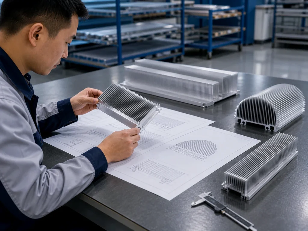
Request the right evidence
Keep the selection record concise:
For the proposed aluminum heat sink, identify the thermal resistance path, temperature references, heat load and cooling conditions. Connect the performance evidence to the exact geometry, mounting, interface and finish. Record assumptions and provide the agreed validation against the application’s acceptance requirement.
Review the supplied sample against the drawing before recurring production. Use an identified first article inspection package for dimensional and delivered-condition evidence.
For cutting preparation, send the profile section, finished lengths and quantities through our contact page. Include the approved thermal-part drawing so the cutting scope follows the intended configuration.
Questions buyers ask
Is lower heat sink thermal resistance always the better purchase?
Compare values for the same defined path and conditions, then check the complete requirements. A number from a different configuration does not settle the selection.
Can a catalog curve replace assembly validation?
Use it as the evidence it represents. Have the responsible engineer decide how the actual assembly should be validated.
Can I scale a catalog value to another cut length?
Ask the manufacturer for the applicable performance data or approved evaluation. Do not assume proportional scaling.
Does cutting accuracy prove thermal performance?
Those are separate requirements. Retain dimensional results and thermal evidence under their respective acceptance criteria.
Manufacturer references
- Boyd: board-level heat sink catalog, selection and thermal-graph guidance.
- Wakefield Thermal: 127712 product listing, a product-specific example of dimensional and thermal field definitions.
- Boyd: thermal interface materials overview.