
Aluminum saw cutting capacity needs a width-and-height combination for the required cut and configuration. A blade diameter or one maximum dimension does not establish whether your complete profile can be cut, supported and clamped.
Start with the section drawing and its intended orientation. Read the relevant capacity diagram and notes with the supplier. Confirm the specific setup and representative trial before treating a fit review as approved production.
Read the complete fit
- Check section width and height together.
- Use the curve or data for the required angle and setup.
- Review supports, clamps and handling as separate requirements.
On this page
1. Read aluminum saw cutting capacity as a dimension pair
Identify what the diagram’s axes mean, their units and the reference position of the profile. Where the horizontal axis is section width and the vertical axis is section height, locate both dimensions as one point. Do not read them as unrelated maximum values.
For example, a diagram’s greatest plotted height may occur at a different width from its greatest plotted width. Combining those two extrema into one rectangular profile can describe a shape the diagram never shows as an available combination.
Elumatec’s MGS 142 technical information directs readers to a cutting diagram for the cutting range. Its 2018 industry catalogue shows angle-labelled curves for width-and-height combinations. That historical diagram illustrates presentation, not a current rating for your machine.
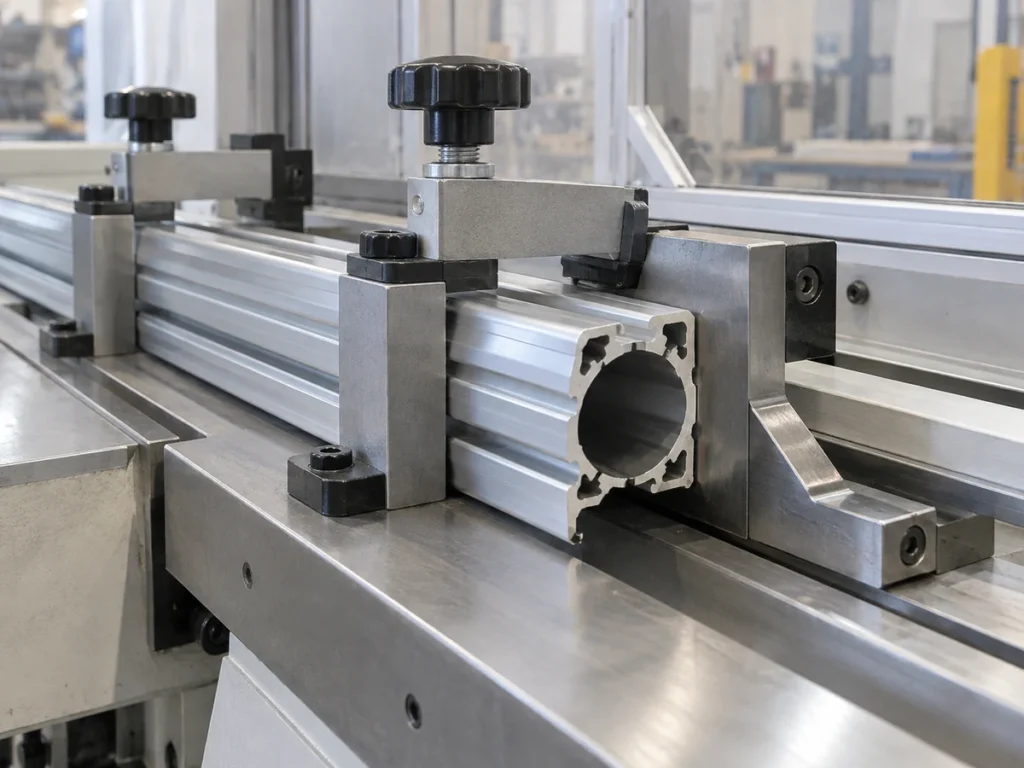
Use the profile’s outer envelope and complete section drawing. A circular opening inside a square extrusion is not the same as a round tube’s outer diameter. Ribs, flanges and other projecting features must remain visible in the fit review.
2. Select the data for the required cut position
Identify the required end cut on the part drawing. Then ask which diagram curve, table entry or configuration applies. A capacity stated for a straight cut should not automatically be carried over to an angled or compound cut.
Check how the manufacturer defines the angle and profile position. The assembled joint angle and the number on a machine display can use different references. Keep the drawing and required orientation available during the review.
If the exact cut position is not covered by the published diagram, request clarification. Do not extend a curve or interpolate a configuration without the supplier’s confirmation. Also identify any required changes between the two ends of a part.
The miter length guide explains long- and short-point references. Those length calculations do not establish the section capacity available at a particular machine angle.
3. Confirm which equipment the diagram describes
Match the diagram to the model, configuration and relevant documentation revision. Identify the specified blade, supports, clamps and accessories where applicable. A similar model name or photograph does not establish that the same data apply.
Blade diameter is one equipment detail. It is not, by itself, the maximum profile height or a complete capacity description. Review the published cutting range and the physical arrangement of the actual configuration.
A section fitting the stated envelope does not establish every other requirement. Material, wall structure, finished length, tooling and part handling still need review. Keep the proposed cut and its required result linked to the supplier’s recommendation.
For a two-head arrangement, review the applicable finished-length range separately from the section envelope. The single- and double-head comparison shows why head count, part size and operating mode are different quotation items.
4. Review support, clamping and the trial
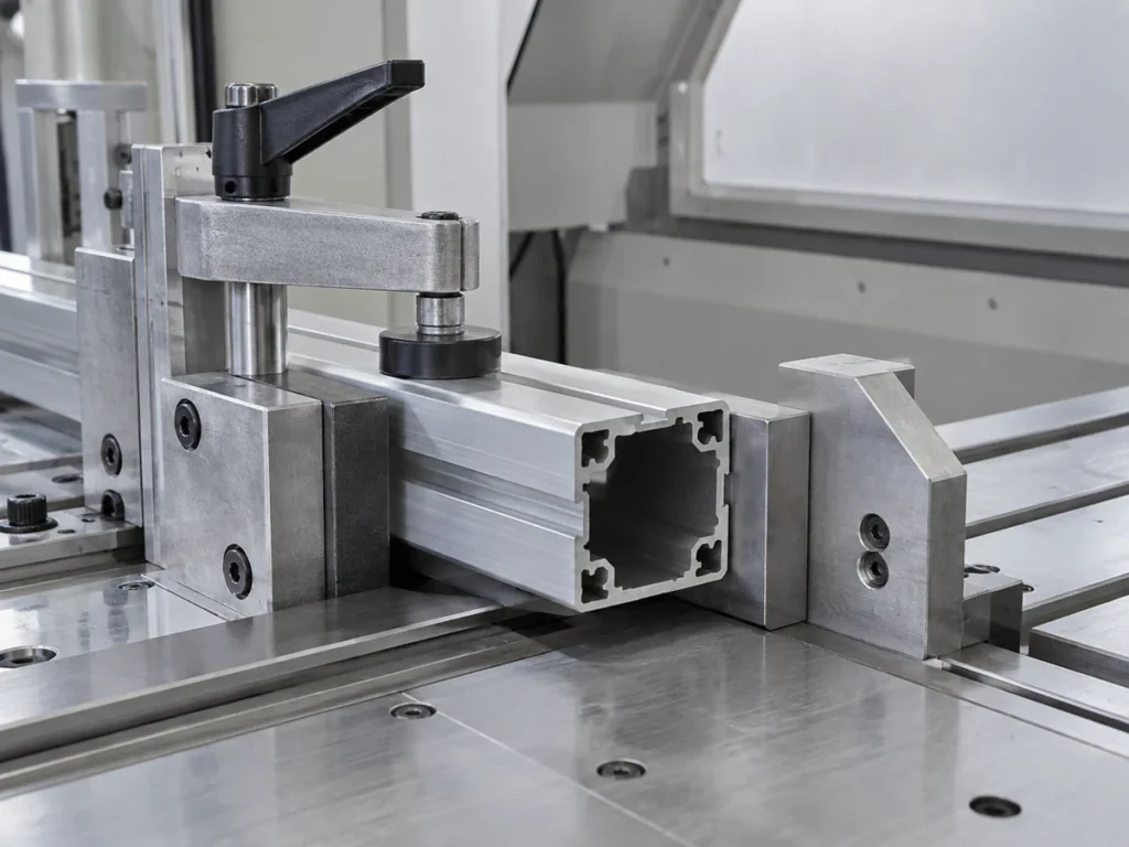
Ask how the actual profile is located and held in the proposed setup. Include thin walls, asymmetric faces and surfaces that need protection. A point inside a plotted envelope is not an approved fixture or an instruction to change clamping.
Identify the incoming stock length and the finished-part sizes. Review support along the stock path and the way cut parts are collected. Section capacity does not establish the minimum finished length or safe handling of every short offcut.
Choose a representative trial that includes the required section and cut position. Agree the finished length, angle, cut-face and surface checks that apply. Keep the samples and results linked to the tested configuration.
Use the cutting tolerance examples to keep drawing limits separate from trial readings. A fit demonstration and a satisfactory finished-part inspection are related but distinct observations.
An 80 × 40 mm section: compare two orientation sketches
Illustrative geometry: a rectangular profile has outer section dimensions of 80 mm and 40 mm. Two candidate orientation sketches put different faces against the references. The example identifies dimension pairs only; neither orientation is an approved machine setup.
| Candidate sketch | Width and height pair |
|---|---|
| A: wider face horizontal | Width 80 mm; height 40 mm. |
| B: narrower face horizontal | Width 40 mm; height 80 mm. |
These are different points on a width-versus-height diagram. Check each candidate against the relevant curve and notes. A favorable fit for one point does not establish a favorable fit for the other.
Then review whether the proposed orientation preserves the required cut direction, reference surfaces and part identity. An asymmetric profile can introduce further requirements that a simple rectangle does not show. Send the complete section drawing.
If the part needs more than one cut position, review the dimension pair and setup for each required operation. Do not carry a straight-cut fit result into another angle without confirmation. Record the outcome separately for each proposed route.
Prepare a brief that makes the fit question easy to answer
Send the section drawing with outer width, outer height and relevant projecting features. Mark the intended orientation and required cut positions. Include material identification, finished-length range, stock condition, quantities and drawing requirements.
Ask the supplier to identify the applicable diagram and configuration. Request clarification of any uncertain combination, accessory or operating mode. Keep unresolved items visible in the quotation rather than treating a preliminary fit response as full part approval.
Start with the JiurunCut product range, then send the section and finished-part drawings. Request a configuration review followed by a relevant trial. The illustrative dimensions in this guide are not a published capacity of any JiurunCut model.
Common questions
Can I combine the listed maximum width and maximum height?
Only if the applicable data explicitly support that combined profile and configuration. The extrema may occur at different points. Check the actual width-and-height pair and the relevant diagram notes.
Is blade diameter the maximum cutting height?
No. Blade diameter is a tooling dimension. The available section envelope also depends on the machine arrangement and configuration. Use the manufacturer’s relevant cutting-range data rather than treating diameter as a part-size limit.
Does an internal round opening make the profile a round tube?
No. Describe the outer section and its full geometry. A circular cavity inside a square or complex extrusion does not establish the same envelope or support requirement as a circular outer tube.
Does a section inside the capacity curve guarantee the finished part?
No. Confirm the actual setup, material, required cuts and handling. Then inspect representative trial parts against the agreed requirements. A section-fit review does not establish every dimension, surface condition or production result.