
Waterjet taper vs stream lag concerns two different changes in a cut. Taper compares the width at the entrance and exit. Stream lag concerns the exit position trailing the entrance as the jet moves.
For an aluminum blank, identify which feature the report evaluates. A width comparison at one straight location does not describe the entire contour.
Three checks for a cut sample
1. Identify waterjet taper vs stream lag correctly
Flow’s explanation of taper and stream lag distinguishes a cut-width difference through thickness from the exit point lagging behind the entrance. Its discussion connects that lag with damage at corners.
Keep those observation names in the report. Ask the supplier to identify what its submitted measurements actually evaluate.
Read the feature name with the reading
Retain whether the record concerns a cut opening, an external part dimension or an internal feature. Do not silently move a number between those headings.
Mark the jet-entry and jet-exit sides on the sample record. Keep the orientation recognizable when photographs and measurements are passed to another reviewer.
Ask the inspector to identify the actual measurement method and locations. A note saying “taper checked” leaves those details unresolved.
Keep the supplied part stage visible
A cut blank and a later machined component can have different inspection requirements. Name the stage represented by each record.
If a dimension is left for machining, retain the approved blank requirement on that feature. Keep the eventual finished-component requirement attached to its own stage.
The waterjet and saw-route guide compares delivered shapes and scope. This guide addresses observations on an identified cut sample.
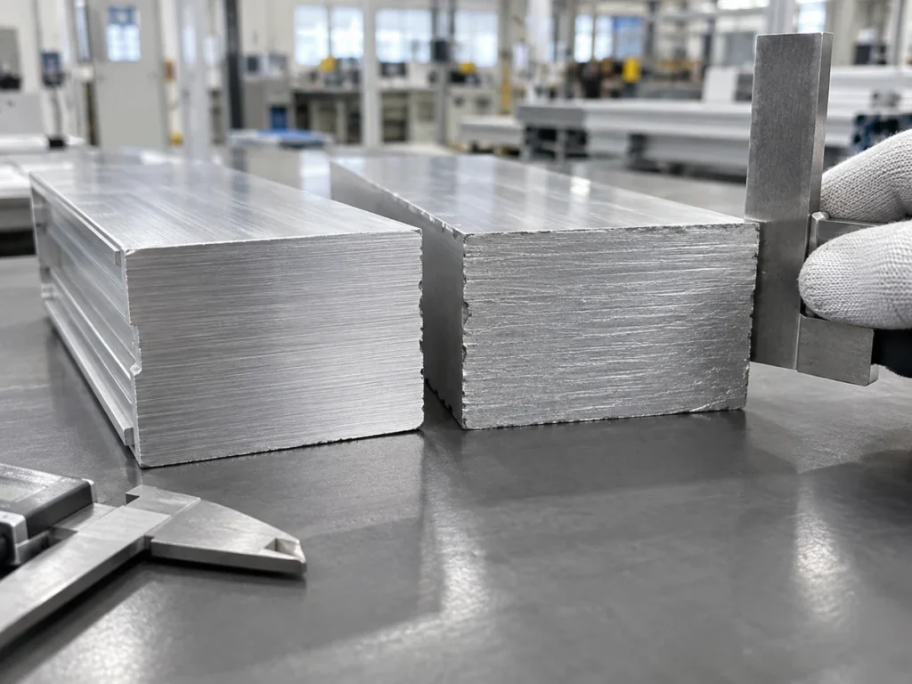
2. Retain the location and meaning of a width comparison
Record each reading with the face and marked location it represents. Preserve the units and the inspector’s description of the measured feature.
A sample photograph can help the reader find the location. Keep the numerical results in the measurement record with the agreed method.
A fictional straight-cut example
For arithmetic only, imagine one identified straight trial cut has an opening width of 1.20 mm at the entry face and 1.00 mm at the exit face. These values are invented.
The recorded opening-width difference is 1.20 − 1.00 = 0.20 mm. That difference describes the two stated opening readings at that location.
It does not identify each wall’s individual contribution. It also contains no exit-position record or corner measurement.
| Recorded field | Meaning of the entry |
|---|---|
| Entry opening: 1.20 mm | Invented opening width at the marked entry face. |
| Exit opening: 1.00 mm | Invented opening width at the matching exit location. |
| Difference: 0.20 mm | Difference between those two opening readings. |
These numbers are not an acceptance limit, recommended cut or measured machine result. No wall angle or complete contour approval is assigned to the example.
Keep the interpretation narrow
If the real report needs a wall angle, request the applicable geometric evaluation. Do not rename an opening-width difference as an angle.
Likewise, an external part size should remain under its own feature heading. Ask the inspector to clarify the relationship when the report mixes part dimensions and cut-opening measurements.
Retain which locations were examined and which remain outside the record. A result at one straight section should stay attached to that section.
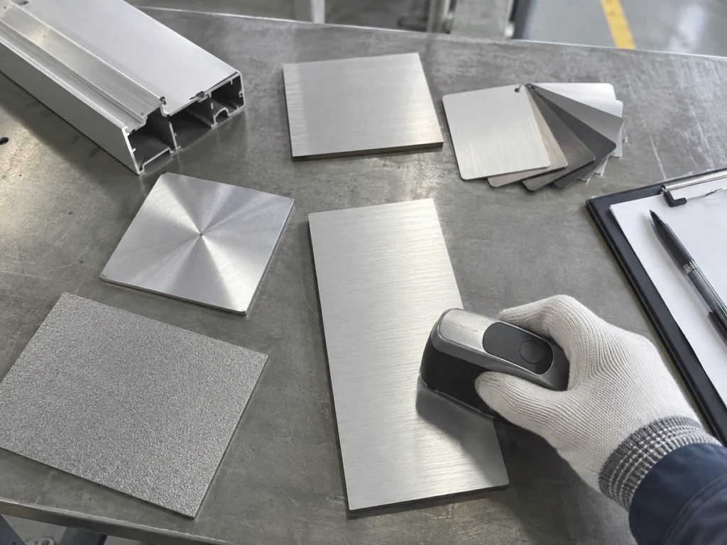
3. Review the required contour and corners
Mark the drawing features that matter to the delivered blank. Include the internal and external contours, corner locations and any specified reference relationships.
Ask the supplier to show which features its sample and report cover. Keep the entry and exit sides identifiable wherever the review needs that distinction.
Separate an outline check from a width check
A width entry at a straight cut and an evaluation of a corner are different records. Keep each with the location and requirement it addresses.
If the report supplies only top-face outline measurements, ask what evidence applies to any other required region. Retain the answer without expanding the measured scope.
Keep the accepted contour drawing and its revision with the sample. A generic photograph of a similar bracket does not establish the geometry of the submitted part.
Separate geometry from visible texture
Record appearance observations where the order requires them. Keep measured feature geometry under its own heading.
The cut-surface roughness guide addresses texture reporting. A specified texture quantity should remain separate from the width or contour entries in this review.
If edge treatment or later finishing is included, name the condition at inspection. Ask whether the report describes the original cut or the part after another operation.
A sample request the supplier can follow
Please identify the entry and exit sides of the attached sample drawing. Mark the locations used for the cut-width comparison and retain the separate contour and corner checks required by the released blank drawing.
Attach the actual aluminum stock condition, thickness and drawing revision. Identify the quantity and delivered stage that the sample must represent.
Ask the supplier to record the tested configuration and observed results. Keep any proposed process change with its own reviewed evidence.
If the proposal mentions compensation, request results for the submitted part. A named machine option alone does not fill the required inspection record.
Keep the purchasing decision tied to the actual blank
Compare quotations at the same delivery stage. State which contours, finishing operations and inspection records are included in each offer.
Keep unresolved features visible in the comparison. Ask the responsible drawing and quality owners to decide whether the submitted evidence meets the released requirement.
For a saw-cut stock request, send JiurunCut the aluminum section and cut list. Identify the required lengths, angles and cut-end checks for that job.
Keep waterjet taper vs stream lag questions with the waterjet provider’s actual part review. This comparison does not identify JiurunCut as a waterjet supplier.
Does the fictional 0.20 mm difference approve a cut?
No acceptance requirement or real result is assigned to that arithmetic example.
Can one straight location establish all corner results?
Request the drawing’s actual feature checks and their recorded locations.