
Aluminum cut surface roughness is a measured texture requirement. A useful quotation identifies the surface, parameter, units, governing specification and inspection method. A bright end face or a “smooth cut” description does not establish a numerical roughness result.
This guide helps buyers prepare those details. It does not set a universal roughness limit or promise a finish from any JiurunCut model. Use the actual part drawing and a confirmed sample evaluation for your job.
Three questions before comparing results
- Were the same surface and parameter evaluated?
- Were the measurement conditions and units compatible?
- Were edge condition, geometry and appearance checked separately?
On this page
Aluminum cut surface roughness answers one quality question
A cut part can meet its finished length and still have an unacceptable edge. It can look attractive and still miss a specified geometry requirement. Write each condition separately so one favorable observation does not stand in for the complete inspection.
| Question | What to define |
|---|---|
| Texture | The roughness parameter and its measurement requirements. |
| Edge condition | Burr removal, edge break or a defined chamfer. |
| Geometry | Finished length, angle or a specified geometric relationship. |
| Appearance | Visible marks and the agreed viewing or reference conditions. |
| Function | The separate assembly or application acceptance checks. |
The same part may need several of these checks. A texture reading does not by itself approve its fit in an assembly. An assembly that fits does not automatically establish that a drawing’s texture requirement was met.
Our deburring and chamfer guide covers the edge requirement. For a different geometry question, see the cut-face squareness guide. Keep their acceptance records distinct from a roughness report.
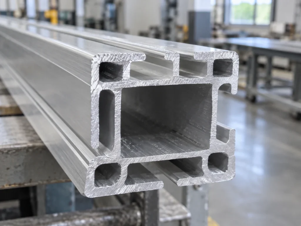
Ra and Rz are different parameter labels
In a profile measurement, Ra summarizes the average absolute height deviations of the evaluated roughness profile. Rz is a height-related parameter with its precise definition tied to the governing standard. The labels tell the reader which characteristic was evaluated; they are not interchangeable finish grades.
Mitutoyo’s roughness fundamentals distinguish these parameters and warn that older uses of the Rz symbol can differ from later definitions. Check the standard edition attached to an older drawing instead of assuming its symbol has the intended current meaning.
A Mitutoyo measurement bulletin illustrates how profile filtering and measurement conditions enter the evaluation. It also distinguishes surface imperfections from the roughness profile. This older bulletin references earlier standards; use it for context, not as an automatic inspection procedure for a new drawing.
For procurement, the practical conclusion is simple: request the specified parameter under the agreed method. Do not change an Rz requirement into Ra with an assumed multiplier. If the required parameter is missing, obtain the appropriate evaluation or a documented engineering clarification.
Five fields make the requirement understandable
1. Identify the exact face
Mark the cut face on the drawing. A hollow extrusion may expose several separate wall areas at one end. State which areas matter and which are accessible for the agreed measurement. Do not leave the evaluator to choose the most convenient surface.
Keep the long extruded surface separate from the new cut face. A report about the outside of the stock does not answer a requirement applying to the end. A drawing reference makes that distinction easier to retain through later handling.
2. State the parameter and units
Write the parameter label beside the numerical requirement and its units. “Roughness 1.6” leaves important information missing. The inspector needs to know what quantity is being evaluated and how the value is expressed.
Ask for the supplier’s report to retain those labels. If documents use different units, have the comparison reviewed before deciding whether the statements agree. A copied number with its unit removed is not a useful acceptance record.
3. Identify the governing drawing and specification
Retain the drawing number, revision and applicable standard edition. ISO’s public overview of ISO 21920-1:2021 concerns the indication of profile surface texture in technical documentation. That overview is not the full standard and does not provide the complete inspection method for your part.
Let the responsible engineering and quality teams resolve an unclear or conflicting callout. A quotation should record the agreed interpretation. Keep it with the accepted drawing rather than leaving it in an informal message that the inspector may never see.
4. Agree the measurement conditions
Ask the evaluator to identify the instrument and the applicable measurement setup. Relevant report fields may include measurement direction, evaluated length, filtering settings and the locations examined. The selected method and governing specification determine which details are necessary.
For a narrow wall or interrupted face, confirm access before promising a report. The available surface must suit the intended evaluation. Do not silently shorten a path, move to another face or change the parameter to obtain a convenient reading.
5. Record the acceptance decision
Agree how the results support acceptance, who reviews them and how unresolved readings are handled. The number of measurements and the decision rule belong in the approved inspection plan. This guide does not prescribe either one for every part.
Keep individual results linked to the sample identity. A single unlabeled screenshot may leave the surface, units and setup unknown. A useful report makes those details clear enough for the receiving team to understand the decision.
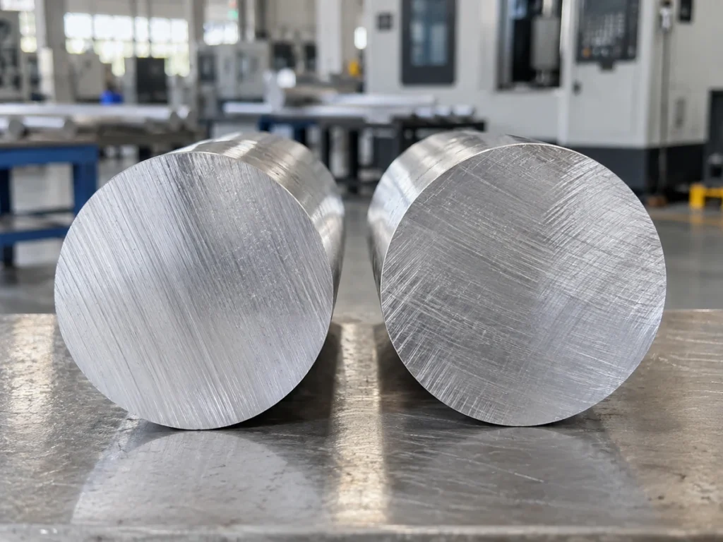
Two incomplete statements cannot prove agreement
Consider an invented document review. The buyer’s note says “Ra 1.6 µm” on the cut face. The supplier’s note says “Rz 6.3 µm” beside a sample photograph. Neither note records the complete measurement conditions or an acceptance decision.
These numbers are examples of labels, not recommended limits, measured results or JiurunCut capabilities. The second statement does not answer the first. The photograph cannot supply the missing parameter or measurement conditions.
The next step is to align the drawing interpretation, then obtain the required evaluation on the identified sample. Keep the original statements visible so the reviewers can see what was clarified. Do not mark the requirement satisfied by comparing the two numerical magnitudes.
Make the sample report useful to the receiving team
Begin with the sample identity, material and section drawing. Identify its cut-face location and the processing stage at the time of measurement. Attach the agreed specification and the instrument or method information needed to interpret the results.
A photograph helps show where the sample was examined. Include an orientation mark or drawing reference when needed. Use the photograph as location evidence, while the measurement record carries the numerical texture result.
Record the results and their disposition separately from burr, length and appearance checks. If a condition remains unverified, label it as open. Passing one part of a sample review does not close the other requirements.
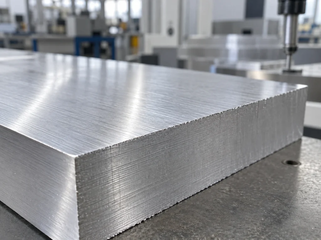
Keep the processing stage visible
If the part will be faced, deburred, coated or otherwise processed after cutting, identify the stage to which each requirement applies. A result on a later machined face does not automatically describe the original saw-cut face.
Likewise, do not present a photographed stock surface as proof of a finished-part requirement. Ask for the requested operation sequence to be included in the sample acceptance plan when it forms part of the machine purchase review.
Common questions
Can a clear photograph establish a numerical roughness value?
A photograph can document visible appearance and sample location. It does not replace the specified measurement. Lighting and magnification also affect how the marks appear to the viewer.
Does a roughness result prove that the edge is burr-free?
Keep the edge condition as a separate requirement. A texture report for an evaluated face does not automatically approve projections at its boundary. Record the agreed edge inspection and its result.
Should every aluminum cut part have the same limit?
The part’s function and drawing govern the requirement. Ask the responsible design team to specify what is needed. A limit borrowed from another part is not a substitute for that decision.
Send the cut-face requirement with your drawing
Ask JiurunCut to review your section and sample requirements. Include the marked surface, parameter, units and applicable specification. Request job-specific evidence for the agreed condition before accepting a finish claim.