
A thin burr at the end of a reflector channel may be invisible in a length report. It becomes obvious when the liner stops halfway into the housing or an end plate rocks against the cut face. For an OEM buying UV-C fixture housing cutting, the useful question is therefore not just whether the saw reaches a nominal length. It is whether the approved aluminum blank remains ready for the next controlled assembly step. Three specific risks are a damaged liner channel, an end plate that will not seat, and a section distorted by clamping.
This article concerns an unpopulated, approved aluminum housing member. It does not propose cutting a complete UV-C fixture, a lamp, wiring, a reflector liner, or a field replacement part. The fixture designer owns optical performance, electrical protection, exposure control, sealing, mounting, and regulatory decisions. A saw supplier can help establish a repeatable cut on the specified metal section and document the resulting blank.
Table of Contents
Identify the extrusion before deciding where to cut
Real UV-C products show why a universal “lamp housing” quotation is unsafe. American Ultraviolet describes an IP55 utility fixture with an extruded aluminum housing, a replaceable reflector liner, and optional mounting brackets fitted to end plates. Signify’s upper-air fixture leaflet also lists aluminum housing and reflector materials, but its ceiling-mounted construction is different. Neither document specifies a Jiurun cutting setup or establishes that another manufacturer’s section is interchangeable.
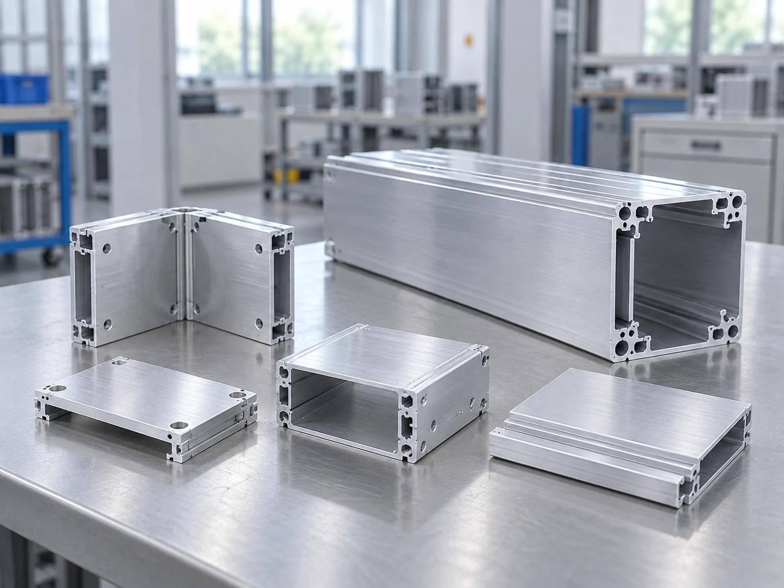
For UV-C fixture housing cutting, ask the buyer for the released section drawing, alloy and temper, supplied stock length, finish condition, section orientation, revision, and a physical sample. Mark which feature is the reflector channel, which faces can touch a clamp, and which end will meet the plate. A photo of the assembled luminaire cannot answer those questions. If the housing is made from sheet, casting, or an already assembled electrical product rather than a saw-cut extrusion, route the request to the responsible process owner instead.
Follow the liner path through the cut end
In UV-C fixture housing cutting, a removable reflector liner changes the acceptance question. The housing may pass overall length and visible squareness while a curled lip or trapped chip obstructs the liner’s insertion path. On the drawing, identify the entry edge, retention groove, clearance to the liner, and any end feature that the saw could touch. Specify whether the liner is inserted before or after cutting. For a bare extrusion, the normal starting assumption is to cut and clean the metal before the liner is installed, but the fixture OEM must confirm its actual process.
Do not convert an unverified “burr-free” marketing phrase into a pass criterion. Agree on a measurable cut-edge requirement: where burrs are inspected, whether a permitted deburring operation is included, and whether that operation may round a retention lip or damage the finish. A simple go/no-go liner fit check can complement dimensional inspection if the OEM supplies the approved liner and assembly method. The result is evidence for that section and method, not a claim about UV output.
Set the end-plate datum separately from overall fixture length
For UV-C fixture housing cutting, the end plate may carry mounting hardware, electrical entry, sealing features, or fasteners; the specific arrangement belongs to the fixture design. Its seating face can be more important to the saw blank than the finished fixture’s catalog length. Release a body cut length measured from named housing faces. Show whether one end or both ends must be square, whether the ends are handed, and which screw bosses or channels must remain open. If the plate requires drilled or tapped features, put them on a separate controlled operation unless the purchase order explicitly includes them.
Two dimensions must not be silently merged: the bare extruded body length and the assembled fixture envelope. An end plate, gasket, bracket, or cover can add to the envelope. Ask the OEM to show its stack-up and inspection datum. If a supplier measures from a cosmetic outer radius while the OEM measures from an internal plate seat, both parties may report “correct” numbers and still fail assembly.
Trial UV-C fixture housing cutting on the actual section
For an equipment inquiry, send the saw supplier an unassembled length of the real extrusion and the released cut drawing. Identify the protected reflector groove, finish faces, and allowed jaw contact. Ask the supplier to propose support and clamping for the weakest wall, then record the exact setup used for the first-off sample. A cut made on a different solid bar may demonstrate machine motion but cannot validate this thin-wall section.
Observe where the profile contacts the infeed, fixture, and outfeed. Check that the jaw does not pinch the liner channel, that short cut pieces remain supported, and that chips are removed before the fit check. If a protective film or coating is already present, inspect both the contact marks and the cut edge. If coating will occur later, show that route on the traveller so the trial does not pretend to approve a finished surface it never saw.
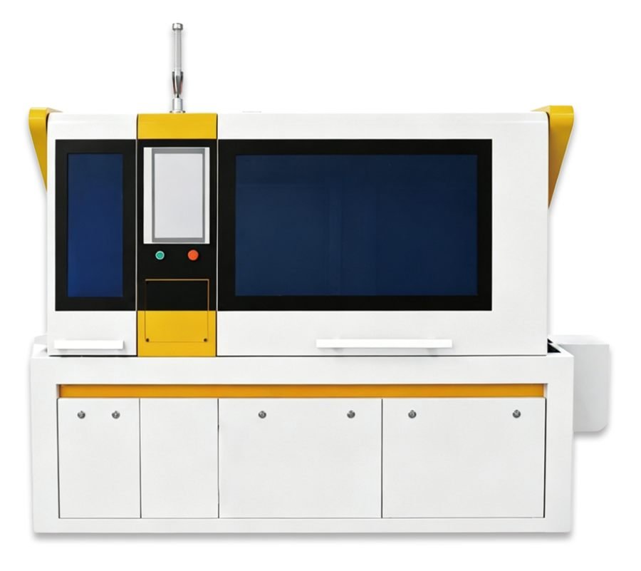
The following short video from Jiurun’s own channel shows a saw and aluminum profile feeding in a workshop. Watch it to discuss feed and clamp access; it does not show this UV-C housing, its liner, or any approved performance test.
Release the first-off blank with a dry assembly check
A UV-C fixture housing cutting trial report follows the part through four hold points. First, identify the extrusion lot and drawing revision, then record the saw setup and blade used. Second, measure body length and end condition from the approved datums, with the inspection method named. Third, inspect the liner channel and remove loose chips without altering a critical lip. Fourth, let the fixture OEM or its designated assembler check the approved liner and end plate on the sample. If a component is unavailable, record that the assembly gate remains open rather than passing it by assumption.
Retain photos of both cut ends and the protected channel, plus the measured values and any nonconforming sample. A one-piece first-off is a setup release, not a process-capability claim. If the purchase is for production equipment, define a representative run covering the longest and shortest approved blank, stock replenishment, and any profile variation that matters to clamping. The buyer decides how many parts and what sampling plan are sufficient.
Keep UV-C approval outside the saw quotation
The cut supplier should not certify irradiation, germicidal effect, electrical safety, ingress protection, or safe exposure from a metal blank. Those require the completed fixture and its designated tests. This separation matters because UV-C exposure can harm eyes and skin; the fixture OEM and installer must control the finished system. The saw inquiry can state the boundary plainly: supply and inspect only approved aluminum body blanks; the owner of the luminaire controls all optical, electrical, sealing, and installation approval.
Related cutting problems are covered in our recessed LED channel article, where bracket positions change the useful blank length, and our clamp-contact guide. They offer process context, not substitute drawings for a UV-C fixture.
Send a cut-ready request
To discuss UV-C fixture housing cutting with Jiurun, provide the released bare-extrusion drawing and revision; stock photos and a physical sample; body length and named measurement datums; protected groove and finish faces; end-plate/liner fit method; required cut-edge and cleaning criteria; expected shortest and longest blanks; and the required trial report. Identify which post-cut work the OEM or another supplier performs. We can then review an appropriate aluminum circular-saw cutting route against the actual section and hold points, without treating a saw demonstration as fixture approval.