
Parcel dimensioning station frame cutting starts with a clear purchasing boundary. An aluminum saw can produce released members for a station frame; the finished dimensioning, weighing, scanning, conveyor, controls and safety functions still need their own design and acceptance. For a buyer, that distinction decides what belongs on the cut-part quote and what must stay with the equipment integrator.
Dimensioning systems may sit beside or over a conveyor, and the surrounding hardware can combine several functions. Cubiscan describes in-motion dimensioning, weighing and scanning as an integrated application. Its warehouse automation overview also separates these functions in an end-of-line workflow. Those references describe system context; they are not specifications for JiurunCut equipment or evidence that any pictured frame is a dimensioner.

1. Parcel dimensioning station frame cutting: define the supply boundary
Write down whether the request is for raw extrusion, saw-cut frame members, a drilled and labeled kit, or an assembled support frame. A complete measurement station is a different purchase. Put the sensor head, scale, reader, conveyor drive, guarding, electrical work and software in a separate integrator scope unless they are expressly included in a supported offer. Ask each bidder to mark inclusions and exclusions on the same drawing revision.
If the project already has a barcode reading portal or a checkweigher frame, do not assume its dimensions transfer. A dimensioning station has its own measurement volume and equipment interfaces.
2. Release a layout that fixes the conveyor interface
Give the frame supplier the station envelope, conveyor travel direction, nominal belt or roller height, support footprint, clear parcel path and accessible service side. Identify where the frame is allowed to attach and where it must clear moving parts. Show the boundary between a free-standing frame and a frame mounted to the conveyor. The integrator should own sensor placement and any clearances required for measurement; the saw supplier needs the approved member lengths and end details derived from that layout.
A useful RFQ contains a plan, elevation and section of the frame with named datums. Avoid a screenshot with only overall dimensions: it leaves the supplier guessing which face controls each cut and whether a corner joint consumes part of the stated length.
3. Specify the profile, finish and stock route
List each approved aluminum profile by drawing or supplier code, section orientation, alloy/temper when specified, surface finish and purchase unit. Call out any face that must remain free of clamp marks. If the OEM supplies extrusion, state its condition and straightness acceptance before cutting. If the saw shop sources material, require equivalence approval before substitution. A visually similar slot profile may not fit a sensor bracket, fastener or panel channel.
For mixed kits, provide a bill of materials with a unique line for every section and length. Keep purchased fasteners, machined plates and electrical brackets distinct from the saw-cut members so a quote does not conceal missing operations.
4. Put cut datums and end geometry on each member drawing
Dimension finished length from explicit faces and say whether the value is the profile blank length or the assembled distance between joints. Mark square or mitered ends, handed parts and any orientation-sensitive cut. Identify the approved tolerance for each length and angle on the drawing instead of asking a shop to infer it from a general frame view. If holes, slots, tapping or deburring are required, say who performs each operation and which features are checked before assembly.
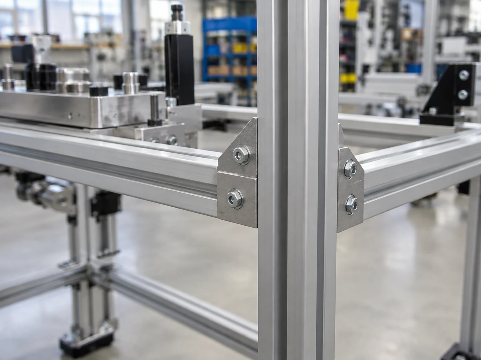
5. Separate structural fit from measurement performance
A frame can be cut to its released drawing and still fail as a measurement system if the sensor mount, weighing section or conveyor interface is wrong. The integrator should define the acceptable station geometry and test the assembled equipment. The cutting shop can report measured member dimensions, end condition and traceability against its own scope; it cannot infer dimensional accuracy, throughput or scanner read rate from a cut blank.
Ask who owns the assembled dry-fit, who signs off the sensor bridge position, and who resolves a bracket clash. Where the layout is still changing, order a first-off kit before releasing a full batch. This limits revision waste without pretending that a first-off frame is a complete station acceptance test.
6. Agree on first-off evidence and inspection method
In parcel dimensioning station frame cutting, the first-off part is a cut-member check rather than a measurement-system approval. For a representative member, record the drawing revision, profile identity, measurement datum, finished length, end angle where relevant, end-face condition and any secondary machining. Name the gauge or method suitable for each drawing feature and agree on the sampling plan. Compare the first-off report with the buyer’s acceptance criteria before the remaining batch is cut.
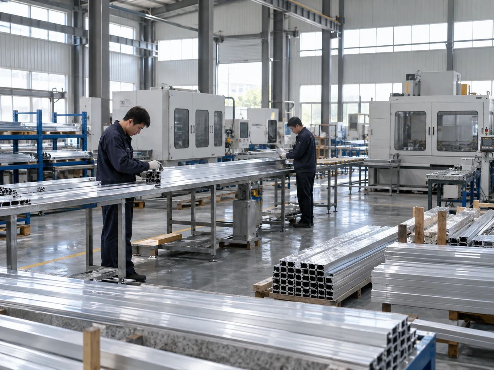
Keep the cut-part inspection record separate from the integrator’s calibration and site acceptance records. This makes a disagreement actionable: a short rail, wrong connector datum and sensor calibration issue have different owners.
7. Control the kit, revision and shipment
Label members by station, drawing line and revision. Separate mirrored parts and protect visible or interface faces in transit. Provide a packing list that maps each bundle to the released bill of materials, with a hold procedure for damaged or mixed pieces. When a layout changes, issue a new cut list and disposition the old stock explicitly; do not silently mix revisions in one station kit.
| RFQ item | Buyer should provide | Saw supplier should return |
|---|---|---|
| Scope | Cut members, secondary work or assembled frame | Marked inclusions and exclusions |
| Geometry | Approved drawing, datum and revision | Cut list and first-off dimensions |
| Material | Profile code, section and finish | Material route and substitution request, if any |
| Handoff | Kit ID and required packaging | Labels, packing list and inspection record |
| System approval | Named integrator or OEM owner | Cut-part evidence only |
What a general saw video can and cannot show
The following video from Jiurun Machinery’s own channel is a general aluminum-cutting equipment example. It illustrates a type of sawing process. It does not demonstrate a parcel dimensioning station, the material or model configuration of this RFQ, a customer trial, measurement accuracy, or a guaranteed output rate.
Common buyer questions
Can the same cut list be used for both a scanner portal and a dimensioning station?
Only after the equipment owner confirms the interfaces and issues a common approved drawing. The devices may occupy different heights, supports and service clearances.
Does a good cut-part inspection prove measurement accuracy?
No. Cut-part inspection checks the member against its drawing. The integrated station needs its own installation, calibration and operating checks.
What should I send to get a useful cutting quote?
Send the released frame drawings, profile list, quantity by member, required cut and secondary operations, acceptance criteria, revision, target kit packaging and the owner of assembled-system approval.
Ready to compare suppliers? Send your approved frame cut list and interface drawings through the JiurunCut contact page. We can discuss the sawing scope and what evidence a first-off cut kit should include before a production release.