
Barcode reading portal frame cutting is a cut-part procurement problem only after the scanner layout and approved frame material are known. A reading portal may straddle a conveyor, support a reader above it, or use a customer-supplied mounting structure. The saw supplier can prepare specified aluminum extrusion members, but a stack of accurate cut lengths does not establish the barcode reading field, scanner alignment or electrical installation.
This checklist helps an integrator decide what belongs in the aluminum cut kit, what remains with the scanner supplier, and which first-off observations are needed before repeat production. It applies when the approved portal design actually calls for aluminum extrusions; do not substitute aluminum for a specified steel frame or certified assembly.
1. Freeze the reading position before the frame opening
The mounting drawing should start at the conveyor and the barcode presentation, not at a generic frame width. Identify the reading station, direction of travel, maximum package envelope and the scanner’s approved location and bracket. The SICK OPS400 operating instructions describe placing a portal frame over a reading position, then installing and aligning the scanner and related detection devices. This describes that manufacturer’s system and sequence; it does not qualify a JiurunCut saw or the pictured aluminum members for an OPS400 installation.
Give the frame designer the actual conveyor interface and any required access or maintenance envelope. The scanner supplier or system integrator determines the reading geometry and bracket adjustment range. The cut shop needs the released member drawings and measurable cut-part criteria. It should not infer a scan angle from a frame sketch.
2. Release a member schedule, not just an overall opening
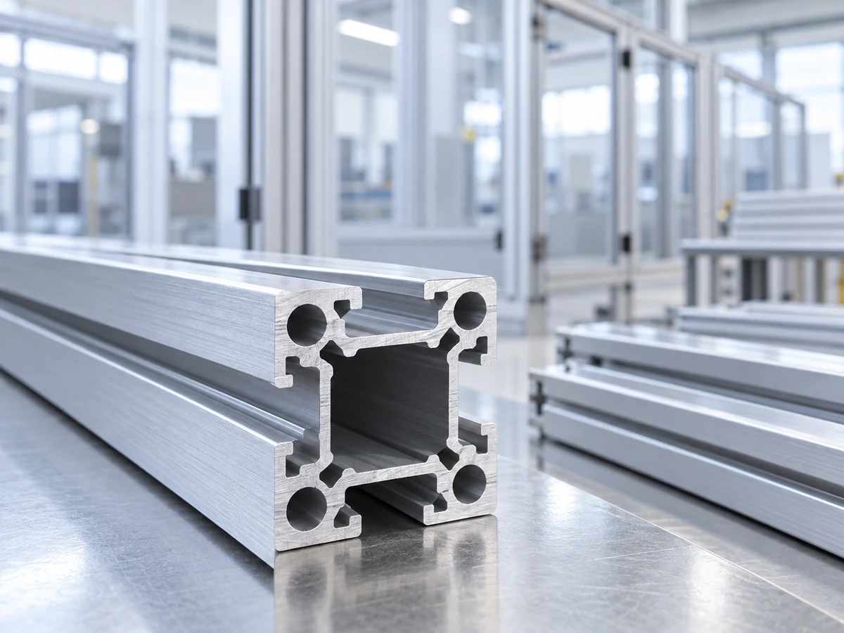
For an approved aluminum portal, list each upright, crossmember, scanner-support rail and any diagonal or secondary member separately. Record the extrusion section and revision, cut quantity, finished length, orientation and part number. State whether brackets, gussets, plates, feet and fasteners are supplied by the frame vendor, scanner vendor or site installer. A portal drawing may show a finished opening while hiding whether the crossmember overlaps the uprights or fits between them; the cut lengths cannot be safely inferred from that drawing alone.
Identify the structural datum used to locate the assembled portal to the conveyor. A floor-to-top dimension, a conveyor-top-to-reader dimension and an individual extrusion length answer different questions. Put the first-off measurement on the released cut drawing, then let the integrator inspect the assembled frame and reader alignment as a separate acceptance stage. If the site conveyor changes height or position, revise the assembly drawing before recutting a batch.
3. Keep mounting and electrical responsibilities explicit
A bracket hole or slot position can be more consequential to installation than the outer frame length. Obtain the exact reader and bracket part references; state which features are already present in the extrusion, which are drilled or tapped later, and who signs off on any machining. The Cognex DataMan mounting guidance gives a product-specific example of a bracket secured to off-the-shelf aluminum profiles with drop-in nuts. That does not mean its fasteners, electrical requirements or profile choice apply to another reader.
Keep cable routing, protective guarding, grounding, trigger sensors and software commissioning on the integration checklist under qualified owners. The cut kit can reserve clearance called out by their drawings, but the saw vendor cannot verify those system functions by measuring cut lengths. If a reader may be repositioned, specify the adjustment allowance in the approved bracket and support-rail design, not as an undocumented change to the saw program.
4. Trial the real extrusion and its cut faces
For each approved section, agree how it sits against the fence, which face receives clamp contact and how a long member is supported on infeed and outfeed. An open slot or hollow section may present a different contact surface when rotated. The first-off record should include the drawing revision, stock identity, datum, finished length, end squareness and any cut-edge or surface condition that could affect a bracket or connector. No universal tolerance or burr allowance can be inferred from a generic portal photograph.
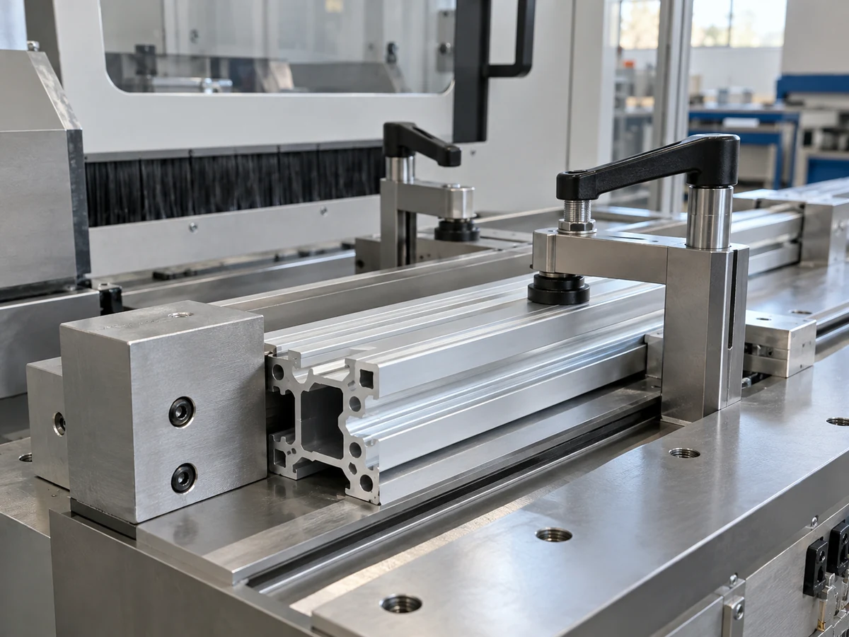
Use the approved bracket and frame connector in a separate dry-fit check when the buyer requires it. Record who performed the fit, what was measured and what remains unverified. Passing that check means only the listed sample and criteria passed. The reader still needs its own setup and scan validation at the installation.
5. Quote the right deliverable
A buyer can request loose cut blanks, a labeled frame kit, an assembled but unequipped support frame, or a complete reading station. Those scopes require different drawings, controls and suppliers. For a cut-blank RFQ, provide the member schedule, approved profile samples, monthly or batch volume, cut-edge criteria, first-off plan and packaging/labeling requirements. If a full station is wanted, assign reader mounting, alignment, trigger devices, wiring, commissioning and on-site acceptance in a separate integration scope.
Transport and site installation can also change the member strategy. A long crossmember may be shipped as one piece or designed with approved joints. The integrator decides joint locations and load path; the cutting supplier then quotes the released part lengths. A job traveler should link stock lot, cut program revision, first-off approval and the labeled kit so the installer does not mix old and new frame revisions.
Barcode reading portal frame cutting: a release checklist
- Reading envelope: Approved conveyor reference, package envelope and reader location supplied by the integration owner.
- Frame design: Material, member drawings, joints, mounting brackets and revision approved by the frame designer.
- Cut kit: Part-numbered upright, crossmember and support-rail quantities, length datums and end conditions released to the saw shop.
- First-off: Actual profile, cut-part measurements, bracket/connector dry fit if required, named approver and recorded open issues.
- System handoff: Reader alignment, cabling, grounding and scan acceptance retained by the responsible integrator.
This is distinct from a camera stand that holds one vision device: a reading portal may span a conveyor and coordinate multiple mounting references. For a related but different frame handoff, see our machine vision camera stand cut-part guide.
What a general saw video can show
The Jiurun Machinery video below is a general saw-equipment example. It can prompt questions about stock positioning, clamping and cut-part handoff. It does not show a barcode portal, a SICK or Cognex installation, a specific approved profile, a customer project, or performance under a scanner trial.
Next step: If your approved portal uses aluminum extrusions, send the member drawings, bracket references, cut list and first-off criteria to JiurunCut for a defined cutting-machine inquiry. The scanner and integration owners should release the reading geometry and installation scope before anyone commits to a production kit.