
A visible opening at a mitered aluminum frame corner is a reason to pause release, not an automatic instruction to cut two new members. The same apparent gap can come from an incorrect cut reference, reversed part orientation, an obstruction at the joint, an unseated connector, or a frame that has been pulled out of square during assembly. A buyer of outsourced cut parts should ask for evidence that separates those causes before authorizing recutting or accepting a concession.
This guide is for a mitered aluminum frame corner gap found during sample fit-up or kit receiving. It describes a decision record, not a universal gap tolerance. Use the approved drawing, the specified profile and connector system, and the assembly method for the actual project. Do not treat a photograph or a general machine video as dimensional proof.
Mitered aluminum frame corner gap: freeze the reference
Ask the supplier and assembler to identify the released drawing revision, profile section, finish, two member IDs, left/right or face orientation, and the connector or corner key specified for that joint. Mark the dimension reference on the cut list: outside point, inside point, centerline, or another defined datum. A correct length measured from the wrong end point can still produce a poor assembled result. The same applies when a part with a correct angle is turned over or paired with the wrong handed member.
Record the intended assembled frame dimension and the agreed method for checking the corner. If the drawing is silent about permitted visible opening, do not invent a pass/fail number at receiving. Request an approved fit criterion from the design owner. The manufacturer’s SignComp commercial kit guide distinguishes cut-to-size mitered members from the corner angles or keys that accompany them; that is a useful reminder that a cut list alone may not define the complete joint.
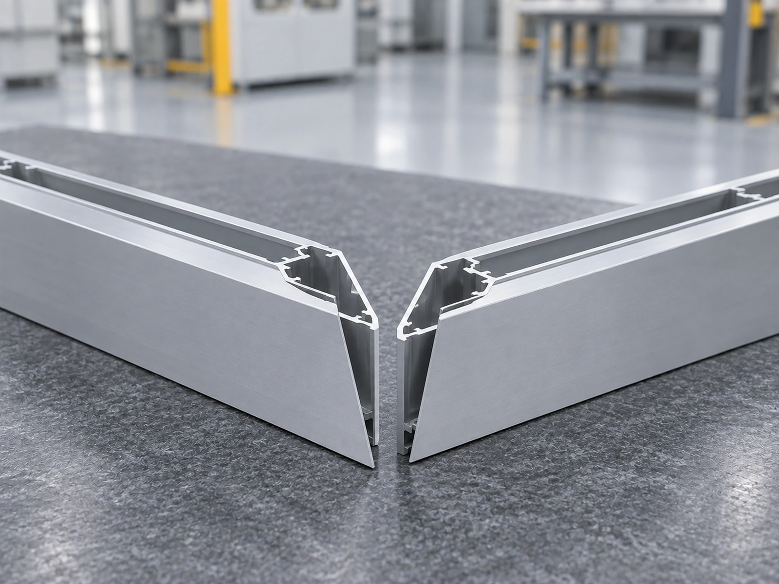
Separate a part problem from an assembly problem
Start with the two identified members on a clean, stable surface. Check whether the ends meet without forcing the pair and whether there is a chip, burr, protective film fold, damaged edge, or other interference at the contact area. Preserve the as-found condition with clear photos before cleaning or deburring. A trial that changes several variables at once cannot show which correction mattered.
Then compare each loose member with its own released length datum and cut-face orientation. For a miter, record where the measurement starts and ends on both sides of the section. If one part is out of specification, note its ID and whether the proposed recut will still yield the required finished length. If a cut face is visibly damaged, that is a separate finding from a length or angle error. Our mitered part length reference explains why measurement points must be agreed before comparing values.
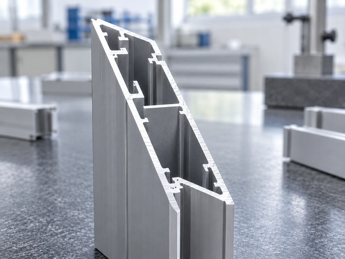
If both loose members satisfy their individual requirements, check the joint hardware and assembly sequence before blaming the saw. Verify that the intended connector is present, seated and compatible with the profile, and that a fastener has not pulled the members out of alignment. Check that the supporting surface and temporary clamps are not distorting the corner. Item’s frame assembly tips show that temporary positioning aids can matter when making accurate frame corners. This is a principle for investigation, not permission to substitute an item part into a different frame system.
Check the whole frame without hiding the local symptom
A corner can appear closed while the overall frame is still out of shape. Conversely, an out-of-square assembly can open a previously acceptable miter. Record the frame’s overall dimensions and diagonal or perpendicularity checks at defined points, with the connector state noted. Compare those results to the actual drawing rather than assuming a generic tolerance. The item conveyor assembly guide calls for perpendicularity and parallelism checks with a measuring square in its own system; the method illustrates why assembly geometry needs its own evidence. Our frame diagonal check discusses the separate role of a frame-level measurement.

Use a cause-and-release record
A useful report should contain the part IDs and lot, drawing revision, profile and finish, connector identification, as-found photos, measured locations, instrument and method, assembly state, and the decision owner. Keep observations separate from assumptions. For example, “light is visible at the outside face” is an observation; “the saw cut the wrong angle” is a hypothesis until the individual parts and joint have been checked.
Choose recut or replacement when an identified member fails its approved cut requirement and the design owner accepts that as the cause. Specify which member changes, its revised length/angle/hand, finish implications, and how the new mating pair will be verified. Choose assembly correction when the loose members comply and connector seating or frame alignment explains the opening; document the corrected assembly method and recheck the frame. Hold for engineering disposition when the drawing lacks an acceptance criterion, the cause remains ambiguous, or the proposed repair would alter a critical interface. Do not conceal a gap with sealant, forcing, or undocumented machining merely to make the photograph look acceptable.
For outsourced parts, keep the decision tied to a traceable lot and retain the rejected or suspect pair until the agreed evidence is complete. If a defect is found only after assembly, the assembly-stage containment plan covers isolation of affected kits. The broader cutting rework release checks apply if an approved repair is chosen. This article’s narrower question is which part, joint condition, or frame setup actually caused the visible corner opening.
What to send with the next cut-part inquiry
Send the released drawing and a marked corner sketch, both member IDs and handed orientation, the connector specification, finish and any protective layer, agreed dimension datums, and the acceptance method for a mating pair and complete frame. Ask for photos of a loose pair and a documented fit-up using the intended hardware. If the job has more than one profile section or angle, name the combination that matters rather than accepting a single convenient demonstration as coverage of the whole order. Our rectangular tube corner trial gives an example of defining a mating pair before selecting cutting equipment.
For a saw quotation, request a trial with your actual profile, hand and end geometry, then review the cut members and assembled result against the same drawing. An automatic feed or clamping sequence may help repeat a cut, but a general machine demonstration does not validate the mating corner on your material. The JiurunCut channel video below is general equipment footage showing feeding, clamping and cutting. It does not show this profile, connector, customer order, corner-gap diagnosis, trial result, or guaranteed accuracy.
When the acceptance reference and cause are documented, you can decide whether to keep the parts, correct assembly, rework an approved member, or commission new cut parts without losing the evidence behind that decision. Send JiurunCut your profile drawing and proposed trial pair if you want to discuss a saw quotation for the specified frame work.