
Use the endpoints marked on the finished-part drawing to define your mitered aluminum part length. With angled ends, the long-point span, short-point span and centerline span can be different on the same piece. Before choosing a saw, show Jiurun which two points define the required length and ask how the proposed setup uses that reference.
Three spans on one angled member
The generic top-view example below shows a flat member with both ends sloping inward toward its shorter edge. Three horizontal spans can be marked on that one shape:
- Long-point span: between the two outer tips along the longer edge.
- Short-point span: between the two inner tips along the shorter edge.
- Centerline span: between the two end faces where the marked centerline crosses them.
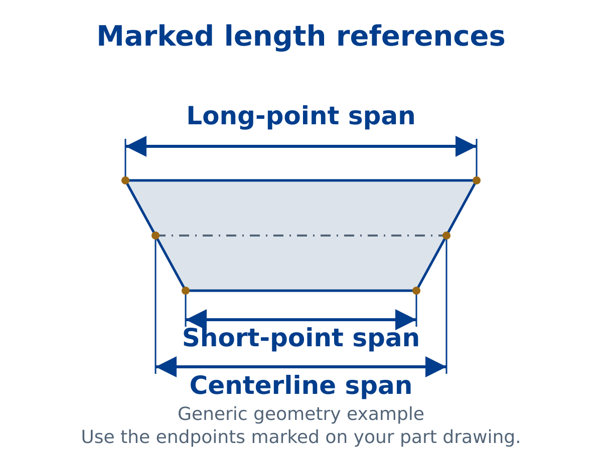
These labels describe the example. Your real extrusion may have grooves, offsets or ends facing another way. A dimensioned view should show the actual profile and the endpoints that matter for your part.
Which points define your finished length?
Send a drawing with the two endpoints marked so the part and the proposed saw setup can be discussed together.
One length label can hide two meanings
Imagine that two people discuss the same angled member. One means the distance between the long tips. The other means the distance along the shorter edge. Both may say “the part length,” while referring to different spans.
A clear drawing removes that ambiguity. Keep the dimension line and its endpoint marks visible when sharing the part. If your cutting list uses a short label, connect it to that drawing rather than leaving the supplier to guess which span it means.
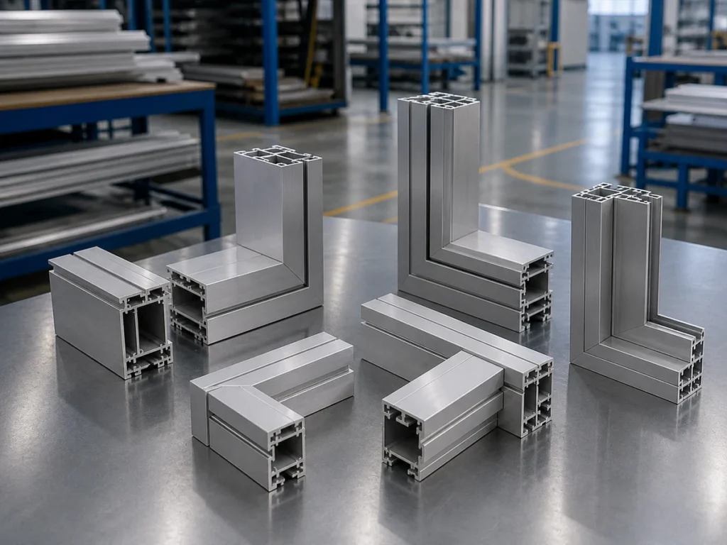
The size of an assembled frame is a separate question. Our panel and frame-length guide explains why a panel size or clear opening should not simply be used as a loose member’s cut length.
Ask how the proposed machine uses the drawing reference
An automatic feed or positioning feature does not tell you, by itself, which points a length value represents. Ask the supplier to explain the proposed setup using your actual part drawing.
A useful question is: “Which two points does the length in this proposal describe?” Then ask how that matches the finished-part dimension you need to check. Keep the explanation with the quoted configuration and the part drawing.
You do not need to invent a machine input value before making an inquiry. Start with the required finished geometry. The supplier should explain how that requirement is handled by the proposed equipment.
Share the finished geometry first
Show the section, both end shapes and the marked length endpoints. Ask for the proposal to use the same part reference.
Keep the reference clear when end shapes change
A change in an end’s slope can move the point where that end face meets an edge or centerline. If you revise either end, keep the length dimension on the current drawing and identify the revision in the part list.
For a discussion or demonstration, ask the supplier to show the finished member and identify the points used for the length check. Use the same reference when discussing the normal production parts.
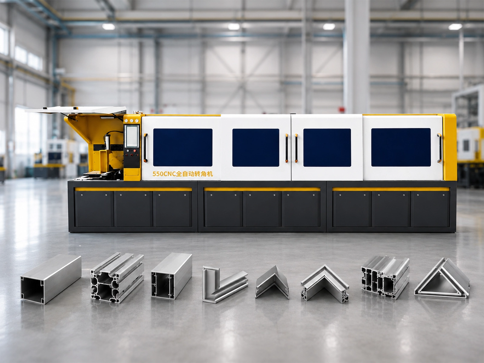
Watch: Jiurun angle-saw demonstration
Use this machine reference when discussing your proposed parts and their length reference.
Discuss your mitered parts with Jiurun
Send the profile section, end shapes and drawing that defines your mitered aluminum part length. Ask how the proposed setup and the finished-part check use those endpoints.
Machine context: Jiurun brochure, physical PDF page 13, through Catalog & Downloads. The diagram illustrates geometry; the length reference for your work must be explained for the actual part and proposed configuration.