
Micrometer vs caliper is a choice about the feature, access and measurement evidence. For aluminum parts, compare the complete measuring arrangement: contact surfaces, range, measuring force and the requirement you need to verify.
A tool name or an extra display digit does not settle the purchase decision. Start with the drawing, then ask the supplier to show how its inspection method addresses the named feature.
On this page
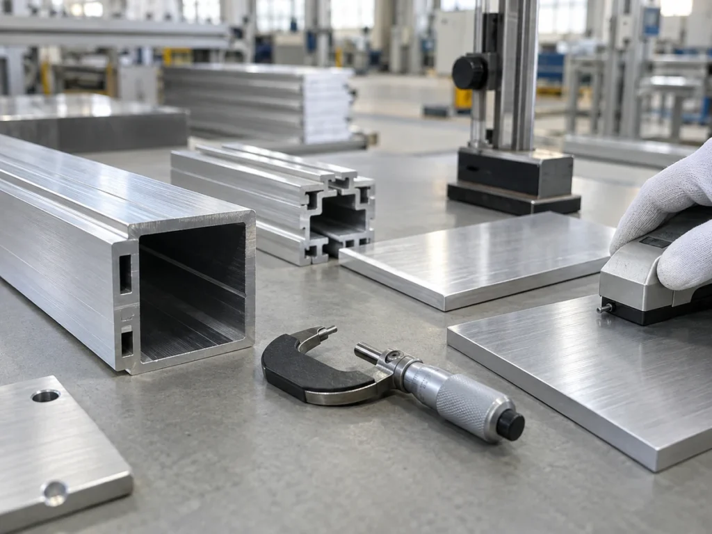
Micrometer vs caliper: what changes?
Mitutoyo’s small-tool overview describes caliper options for outside, inside, depth and step measurements. Starrett’s micrometer overview distinguishes outside, inside, depth and specialized contact arrangements.
That variety matters. A general outside micrometer and a caliper’s inside jaws do not address the same feature. Nor should every micrometer be treated as a standard flat-anvil tool.
| Inspection task | What to establish before choosing |
|---|---|
| Outside size | Contact geometry, range, access and evidence for the specified tolerance. |
| Tube wall | Access to the wall and anvil or jaw suitability for the curved inside surface. |
| Depth or internal feature | Suitable measuring arrangement and reference surfaces for that named feature. |
Compare each tool against the task instead of making one universal ranking. Ask the quality owner to approve the complete measurement method for acceptance.
Check 1: identify the measured feature
Mark the dimension and location on the drawing. Specify whether the requirement is an outside size, wall thickness, slot width, hole diameter or depth.
Keep different dimensions separate on hollow parts. A correct outside reading does not establish the inside size or every wall. Use the aluminum tube dimension guide to organize those fields.
For a cut profile, identify where along the part the measurement applies. If local variation matters, agree on the required locations rather than allowing each supplier to choose a convenient point.
Also state the part condition. A drawing dimension before finishing and a requirement after coating may need different evidence. Preserve the actual delivery-stage requirement in the inspection request.
Check 2: review contact and access
Ask how the measuring faces contact the feature. The supplier should identify the accessible surfaces and any feature that prevents the proposed tool from seating as intended.
Starrett describes tube and rounded-anvil micrometers for cylindrical-wall measurements. It also lists disc, blade and other specialized micrometers for particular geometries. This shows why contact form belongs in the selection review.
For aluminum profiles, show thin walls, fins, narrow grooves and nearby ribs on the section drawing. Request a representative sample review where the contact arrangement is unclear.
- Identify the surfaces used for the reading.
- Confirm clearance for the anvil, spindle or jaws.
- Record the part orientation and support.
- State features outside the method’s scope.
For a feature with one-sided access, consider a separately qualified method. Our ultrasonic thickness guide explains the information needed for that review.

Check 3: compare range and evidence
Request the exact instrument identity and applicable range. Confirm that the planned setup covers the required dimension and can reach the specified locations.
Keep display resolution, instrument specification and actual measurement evidence as separate items. The number of displayed digits is not the complete basis for an acceptance decision.
Ask what reference checks and calibration records support the selected arrangement. Starrett identifies micrometer standards as fixed-dimension tools for basic field checks. Such checks have a stated purpose; they should remain connected to the overall inspection method.
For a tight requirement, have the responsible quality reviewer evaluate the method’s suitability and uncertainty. Do not create a universal tolerance threshold at which all calipers become unsuitable or all micrometers become acceptable.
If a result is close to an acceptance limit, follow the agreed decision process. Preserve the original record and any additional measurement rather than replacing the first result with an unexplained pass mark.
Check 4: define measuring force and support
Ask the inspector how the method controls contact with the part. For thin or flexible features, include the support and contact requirements in the review.
Mitutoyo’s Series 227 brochure provides a specific example of a micrometer with a constant, adjustable measuring-force mechanism and a held reading at the selected force. That feature belongs to the identified product; it should not be assumed for every micrometer.
Do not copy a force value from that product example into an aluminum-part procedure. Have the inspection owner establish a suitable arrangement for the actual feature and confirm it with representative parts.
Where two operators obtain different readings, preserve their measurement locations, contact arrangements and part conditions. Ask the quality owner to resolve the method difference before changing the drawing or blaming the cutting process.
If a thin-wall part needs special handling, our tube wall thickness guide helps connect the section drawing with the receiving requirements.
Check 5: keep the result connected to the part
An inspection result should identify the part and the measured characteristic. Agree on that record before the supplier begins production.
Capture the details that make the result reviewable:
- Part number, drawing revision and batch.
- Dimension and measurement location.
- Instrument and relevant contact arrangement.
- Applicable reference checks and conditions.
- Recorded result and acceptance decision.
Where the instrument supports electronic output, confirm how the recorded value stays linked to its part and location. Mitutoyo’s overview describes data collection options, but a transmitted number still needs an identified inspection record.
For initial deliveries, use the first article inspection package. For recurring batches, retain the agreed connection through batch traceability records.

Prepare the supplier handoff
Send a concise request that preserves the feature and method:
For the specified aluminum dimensions, identify the proposed micrometer or caliper arrangement, applicable range, measuring locations and part support. Provide the reference-check basis and inspection results against the drawing revision. Identify inaccessible features or method changes for review before production.
For cutting preparation, send the section drawing, finished lengths and quantities through our contact page. Include inspection locations and the delivered condition so the cutting and acceptance reviews follow the same requirement.
Questions buyers ask
Is a micrometer always the right choice?
Review the feature and actual instrument arrangement. A specialized internal or wall measurement may require a different tool or contact form.
Does more display resolution prove a better result?
Review the instrument specification, method and supporting evidence. Display resolution alone does not approve the measurement.
Can outside diameter establish tube wall thickness?
Those are different characteristics. Specify the required wall location and an appropriate measurement method.
Can a tool photo replace an inspection report?
No. Use identified results against the drawing and agreed acceptance requirements.
Manufacturer references
- Mitutoyo: small tools and data management overview.
- Starrett: micrometer types and contact arrangements.
- Mitutoyo: Series 227 adjustable-force micrometer brochure. A product-specific example published in 2019; confirm current specifications for an actual purchase.