
A clear LED housing cutting specification defines the extrusion section, the blank length, the required end condition and the surface finish at handoff. Keep that saw-cut blank separate from the completed luminaire. Drilling, connector preparation, cleaning and assembly may belong to later operations.
Before requesting a cutting-machine proposal, describe the part as it should leave the cutting cell. Then show what happens next. That distinction helps the supplier review the actual stock, handling and part checks.
Blank specification checklist
Identify the section before LED housing cutting
Send the supplier’s cross-section drawing and profile reference. Housing extrusions can contain thin lips, enclosed spaces, fins or channels that serve different parts of the lighting assembly.
Hydro’s LED extrusion overview describes integrated features such as clips, screw channels and slide-in compartments. These features explain why outside width and height alone may not describe a housing’s functional geometry.
Identify the specified alloy, temper and finish in the stock information. Include the supplied stock length and normal order quantities. If several housings share one outside size, give each cross-section its own identity.
For the machine review, show where locating and support can act on the actual section. Ask the supplier to review the geometry under the approved setup procedure. A thin feature that fits the finished product may need particular attention during handling and the part trial.
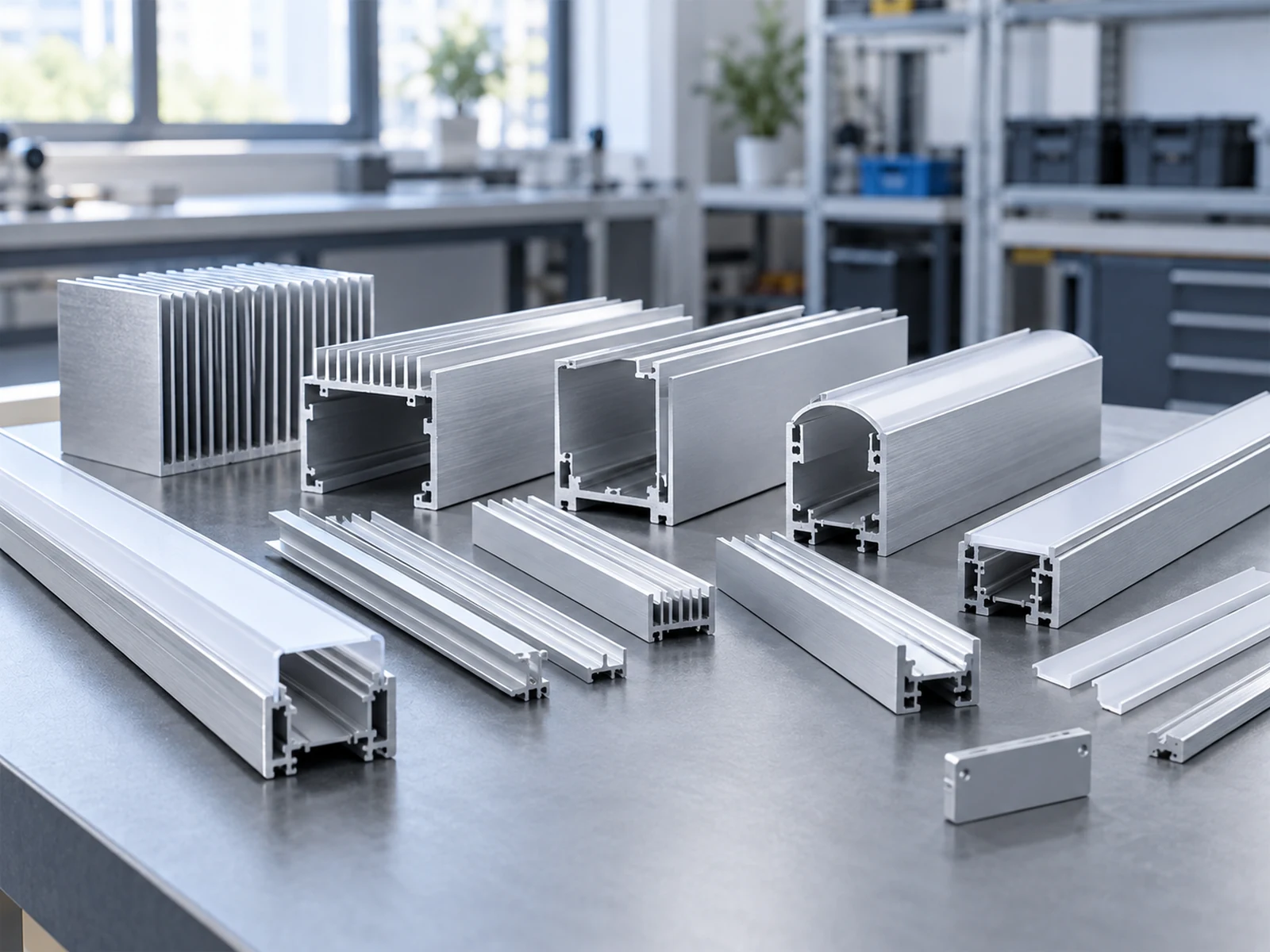
Define the length of the blank, not just the luminaire
An overall product dimension may include end caps, joints or other components. The extrusion body length should come from the approved part drawing or bill of materials.
State whether the saw supplies a final-length housing or a blank for a later operation. If a later process changes the end faces, have the design and process owners define any required stock allowance.
Keep that allowance visible on the controlled blank drawing. Do not ask the cutting operator to guess it from the final assembly dimension.
For a straight-cut housing, define the finished-length reference and acceptance limits. For angled ends, identify the measurement points and the relationship between both ends. The length-datum guide explains how to keep those references consistent.
Two drawings can describe two different stages
A blank drawing tells the saw cell what to deliver. A finished-part drawing tells the later operation what the component must become. Give them clear part or stage references so inspection knows which requirements apply at each handoff.
If the drawing revision changes, review the cut job and any affected stock already in production. A new end-cap design, for example, may change the body length or end preparation required by the assembly.
Describe the required end condition
Use the drawing and quality plan to define the end condition accepted at the saw exit. Specify which dimensions, end geometry and edge condition are checked before release.
Where the end face meets another component, include that interface in the part review. A length measurement alone may not answer whether the approved housing and end component fit together as intended.
Keep the checking method practical and repeatable. Identify the measuring reference and any representative fit check agreed for the trial. Record the result against the blank or finished-part stage actually being tested.
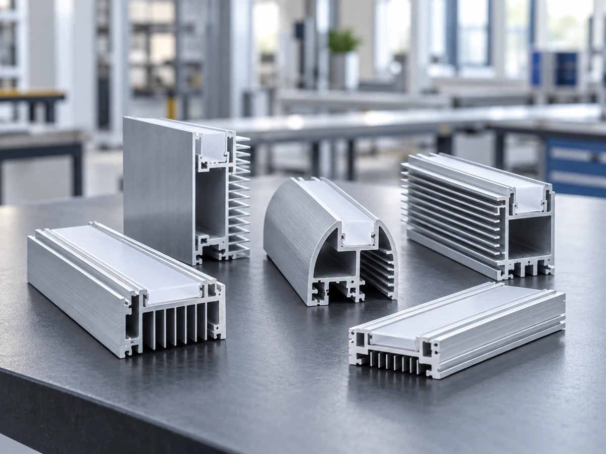
Agree what edge finishing is included
If the order includes edge finishing, specify its scope and acceptance requirement. If the part goes to another operation first, document what condition that operation can receive.
Do not use a broad phrase such as “perfect edge” in place of an agreed criterion. A useful record says what is examined, how it is checked and which requirement determines acceptance.
The extrusion cut-edge guide can help organize the observations you want to make during the part trial.
State the finish and handling requirements
For LED housing cutting, record whether the stock is bare, anodized, coated or otherwise finished. Identify the surfaces that will remain visible in the completed product.
If finishing takes place after cutting or machining, define the surface condition accepted by that next process. If the stock arrives finished, state how newly cut end faces are handled under the approved production route.
Confirm the collection and packing arrangement before the batch begins. Similar-looking housings may differ in finish, length or later feature positions. Keep their identities visible as they move through the cell.
Include surface-marking concerns in the representative trial. Review the part after normal support, locating, collection and handling, rather than looking only at the instant it leaves the cutting zone.
Connect the blank to machining, cleaning and assembly
List the operations that follow the saw. Holes, threaded features, electrical openings or other drawing features need their own process scope. Do not assume that an automatic cutting cycle supplies those features.
Also define the cleanliness required at handoff and who performs the agreed cleaning operation. Use the site’s approved procedure. The cutting record should show whether that stage is included in the delivered blank or occurs later.
For assembly, identify any orientation that must be preserved. A housing with an asymmetric channel arrangement may need a defined reference face when subsequent features are added.
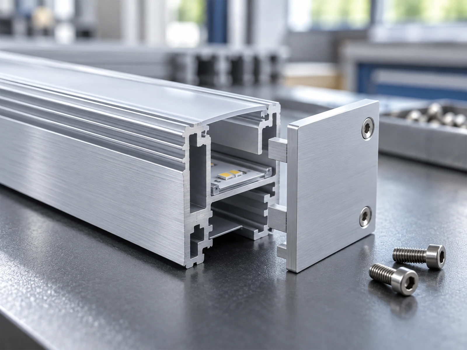
A sample assembly review can help check the agreed interface, but it does not replace the finished luminaire’s electrical, thermal or other product verification. Keep each operation’s acceptance scope clear.
Use a short review sheet for the cutting trial
A representative LED housing cutting trial should use the actual section and the proposed equipment configuration. Include the handling arrangement that belongs in the offer.
| Review item | Information to keep |
|---|---|
| Stock | Profile reference, material and finish |
| Blank | Drawing revision, length and end requirements |
| Setup | Approved fixture and handling configuration |
| Part checks | Method, observations and acceptance result |
| Next operation | Required handoff condition and part identity |
| Output | Produced, accepted and unchecked counts |
If a concern appears, record where it first became visible and which part feature was affected. That gives the supplier a specific issue to review with you.
Keep the result tied to the tested section, blank and setup. A successful review of one housing does not automatically validate every size or finish in the product range.
Prepare your housing cutting inquiry
Send the profile drawing, blank and finished-part drawings, typical batch quantities and the production route. Add photographs that show the actual section and any surface or end condition you want to review.
JiurunCut can discuss an LED housing cutting configuration and a representative trial plan using those details. If you only have an assembly drawing, identify which components belong to the housing so the blank scope can be clarified.
Reference and scope
Application context: Hydro, Extruded Aluminium Profiles for LED Lighting. This article addresses saw-blank planning. Images are illustrative; they do not verify a particular luminaire design or machine test.