
A finished length datum tells everyone where a saw-cut part is measured. Mark the two endpoints or reference faces on the finished-part drawing. For angled ends, show orientation and inside or outside corners. Use the same reference in the cutting list, sample report and production inspection.
Three things to remember
- State where each length starts and ends on the finished part.
- Show angle direction and mirrored-part identity on the drawing.
- Use the same measurement method during trial and production.
On this page
1. Make the finished length datum unambiguous
A straight square-cut bar is relatively simple to describe. A hollow, stepped or angled extrusion may have several edges that could be measured. Two people can report different lengths for the same physical part if they use different references.
Mark the datum and endpoints on the finished-part drawing. If the assembly relies on a particular face or hole position, explain that relationship instead of assuming a stock-cutting dimension tells the whole story.
- Start and end reference
- Inside versus outside length on an angled end
- Drawing units and revision
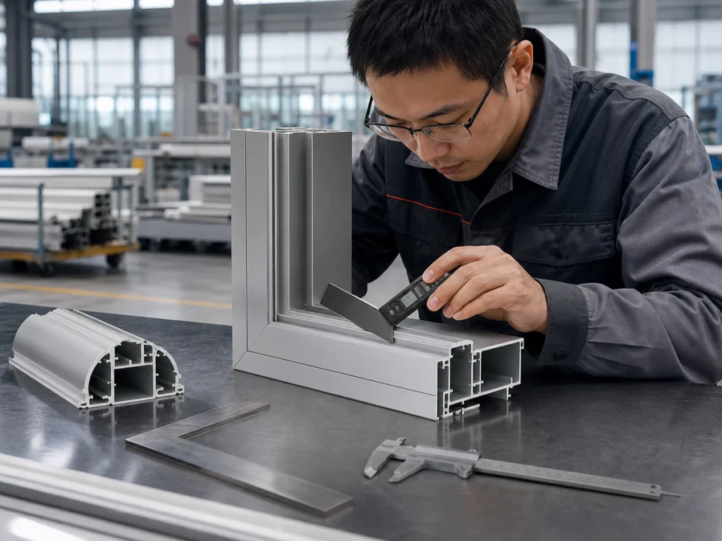
Example: a rail with two mitered ends. Its outside-corner length and inside-corner length are different dimensions. Highlight the finished length datum your assembly uses, label left and right ends and show the angle convention. Do not compare a machine setting measured between one pair of points with an inspection result measured between another pair.
2. Keep length and angle together
For a mitered part, record the angle convention, which end receives the angle and whether the part is left- or right-handed. A single angle value can describe several different finished pieces.
Provide a simple sketch or a marked sample if orientation is hard to explain in words. The miter-cutting guide covers angle direction in more detail.
3. Agree how samples will be measured
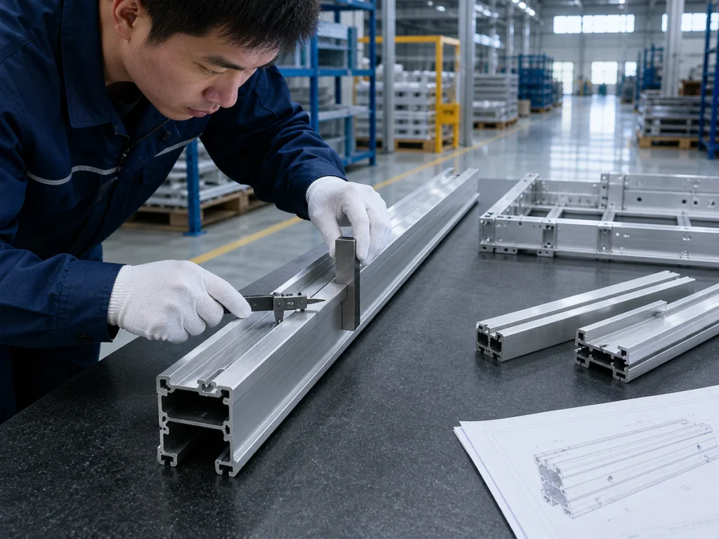
Choose the measurement points, instrument and support method appropriate to the part. Long extrusions may need stable support during inspection; an unsupported piece can give a misleading result.
Record who measured the sample, which drawing revision was used and whether the result is a machine setting or an actual finished-part dimension. The two should not be silently interchanged.
- Measurement tool and contact points
- How the part is supported
- Number and identity of pieces inspected
Straight part
Information to send: Two end reference planes
Question to ask: Are both ends square and accessible to the gauge?
Mitered part
Information to send: Inside or outside corners and handedness
Question to ask: Does the measured length match the assembly drawing?
Repeated batch
Information to send: Sample IDs and measurement method
Question to ask: Are later parts checked against the same datum?
▶ Watch: Positioning Profiles for Angle Cutting
This video shows a machine setup example. Confirm the configuration against your own profile drawing and sample.
4. Separate settings from part acceptance
A quoted positioning or repeatability figure may use a test that differs from your finished-part requirement. Ask what the figure measures and under which setup and material conditions it applies.
The accuracy and repeatability guide explains why those terms must be compared carefully. Your acceptance decision should still rest on parts checked against the agreed drawing.
5. Carry the datum into production records
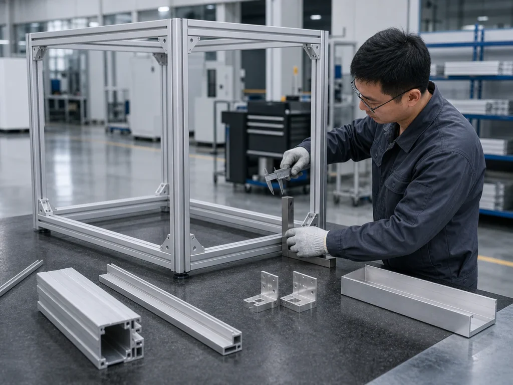
Use the same part ID and reference method in the cutting list, trial report and shop-floor inspection sheet. If the datum changes after a design revision, update the program and measuring instructions together.
When you send a drawing to JiurunCut, highlight the reference points and the assembled use of the part. That makes the first engineering discussion more precise.
Common questions
Can I specify only a nominal length?
It can start a discussion, but the finished-part datum and permissible variation are needed for acceptance.
Does an encoder reading equal finished-part length?
Not automatically. Verify actual cut parts using the agreed reference points and method.
Should mirrored parts share one drawing?
They can if handedness and angle direction remain unmistakable. Otherwise separate part IDs are clearer.
Discuss your cutting requirements
Share the finished-part drawing with the finished length datum highlighted. Include the length range, angles, permissible variation and measuring method. JiurunCut can discuss the cutting setup against those references and agree what a representative sample should demonstrate.
References and scope
This is drawing and inspection guidance; it does not assign a tolerance to a JiurunCut machine or certify a finished part. Recommendations require a review of your drawing, sample and production requirements.