
Keyway dimensions need to describe the correct interface on the correct component. Before comparing quotations, identify the shaft, hub and mating drawing. Keep the width, depth definition, length, location and applicable tolerances attached to that interface.
A note such as “standard keyway” can leave the buyer and supplier working from different assumptions. These three checks help clarify keyway dimensions in the request without choosing a key size or approving a drive design.
Resolve these details first
- Which component and which mating interface does the requirement describe?
- Which drawing controls the complete feature and its inspection?
- What does the cutting supplier deliver before downstream machining?
1. Assign the keyway dimensions to the correct interface
Start with a component identifier. A shaft drawing and a hub drawing are separate documents even when they belong to the same assembly. Label the part number and revision in the quotation, then identify its mate.
If the machine has more than one connection, distinguish each location. Avoid using “the shaft” for both sides of an assembly. A supplier should be able to connect every proposed bore or shaft interface to a specific drawing.
KTR’s RIGIFLEX-HP selection questionnaire provides a useful manufacturer example. It keeps the driving and driven sides in separate columns, asking for shaft type, bore information, tolerance class and feather-keyway information. For straight shafts, it also asks for keyway length, width, additional interface dimensions and the applicable standard.
That questionnaire belongs to a particular coupling selection. Its fields illustrate the need for complete interface information; they do not select a coupling, key or tolerance for an unidentified JiurunCut machine.
Include the component material and condition where they belong in the controlled specification. An aluminum hub, a steel shaft and a purchased key should not share one vague “aluminum part” description. Keep each item identifiable without inferring its properties from appearance.
For replacement work, identify the exact approved assembly and component reference. A photograph can help locate the part, but it should not authorize changing a connection. Ask the responsible supplier for the controlled drawing or replacement specification.
2. Retain the whole drawing callout
A single width does not explain the complete set of keyway dimensions. Keep the approved drawing’s depth definition, axial length, end form, location and relevant tolerances visible in the request. Include the section or detail view needed to interpret them.
Check the reference for each dimension. If a dimension reaches from a bore surface to another feature, preserve that relationship in the drawing. Do not rename it “depth” in an email if doing so changes what the original callout describes.
Separate a key’s dimensions from the keyway requirements on the parts. If a quotation lists only a purchased key designation, ask how the corresponding shaft and hub features are specified. Retain the approved fit requirements rather than inventing them from the key’s nominal size.
Where the drawing cites a standard, identify the applicable document and its use in the callout. Avoid accepting “to standard” without knowing what requirement the supplier is applying. A catalogue reference can help a discussion, but it should not override the released part drawing.
A small example: width and length are separate questions
Consider an invented review in which an approved detail gives a keyway width of 6 mm and an axial length of 24 mm. A supplier’s summary repeats only “6 mm keyway.” The numbers are fictional, not a recommended design or catalogue selection.
Ask the supplier to confirm the 24 mm axial extent and the rest of the referenced detail. The 6 mm entry does not establish the length, location, depth or tolerance. Keep the quoted keyway dimensions tied to the drawing revision so the missing information can be resolved directly.
If a later drawing changes the axial extent, have the responsible team review the proposal again. Do not assume that an unchanged width means the rest of the interface remains approved. Record which revision the supplier has actually reviewed.
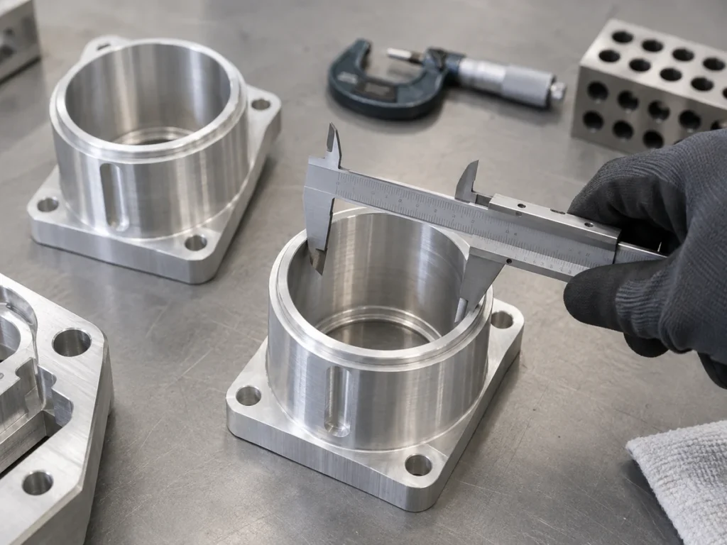
Agree the inspection information with the requirement. A general outside-diameter reading or an image of a circular opening does not establish every keyway feature. The report should identify the actual checks, references and accepted limits from the approved documents.
Our hole-position guide covers a related drawing problem: a feature’s size and its location require their own references. Keep that same document discipline when several features share a hub drawing.
3. Define the blank before comparing cutting proposals
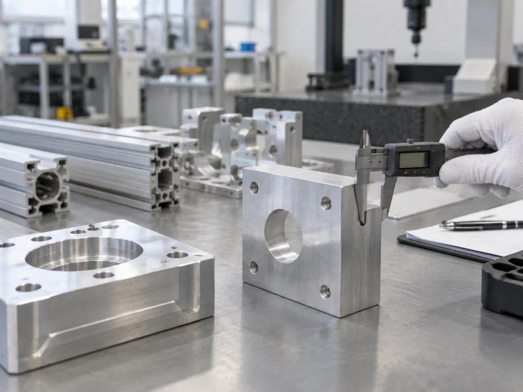
A component that will receive a machined bore and keyway may begin as a sawn blank. Name the required stage in the cutting order. The saw’s deliverable and the assembled drive interface require separate acceptance information.
Provide the approved blank drawing or cutting list. Include material identity, incoming stock section, required length, quantities and end requirements. If later machining needs an allowance, retain the process team’s approved allocation.
The finished interface should remain visible as context. It should not become an instruction for the cutting supplier to guess stock sizes, machining allowance or a connection fit. Have the downstream process owner issue the relevant blank requirements.
Identify the work included in each quote. Sawing, turning, boring, keyway machining and final inspection may be separate operations. Ask where each proposal ends before comparing the price per piece.
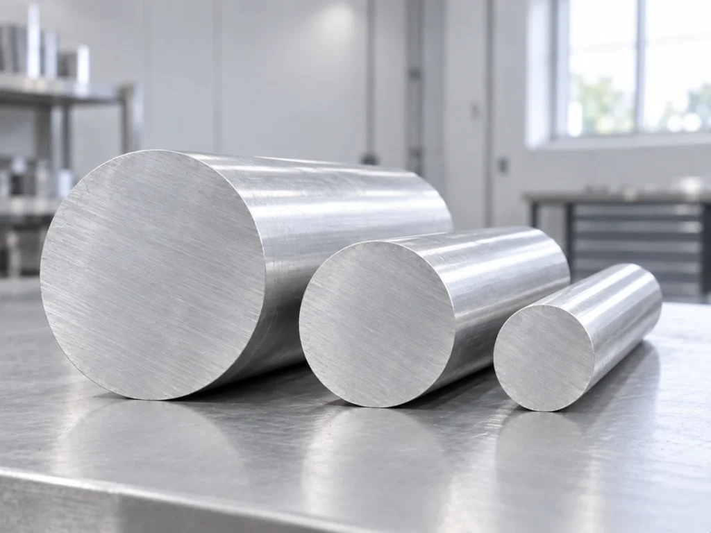
For solid cylindrical stock, our round-bar cutting guide explains how to specify the sawn piece. Review the actual section and blank requirements rather than treating a hollow-profile demonstration as approval of a solid-bar job.
Keep stock and sample identification through the handoff. A sample labelled as a cutting blank should remain distinguishable from a completed machined hub. Record the drawing revision and the operation stage in the review notes.
Questions about keyway dimensions before ordering
Can a shaft diameter determine the entire keyway requirement?
No. Retain the approved interface drawing and relevant standard callout. Ask the responsible designer or component supplier to resolve missing dimensions and tolerances.
Does “standard keyway” identify an accepted fit?
It leaves the controlling requirement unclear unless the applicable document and feature callout are identified. Confirm them in the quotation and inspection scope.
Does a cutting quotation include the finished interface?
Only when the relevant machining and acceptance work is explicitly included. State the output stage so a sawn blank and a completed component are compared fairly.
Prepare a clear blank request for JiurunCut
Send the approved stock specification and cutting list. Include piece quantities, end requirements and downstream machining context. Keep the finished shaft-hub interface on its controlled drawing for review by the responsible process team.