
Aluminum hole position depends on the drawing’s reference scheme as well as the finished part geometry. When a cut blank moves to drilling or machining, the team needs a clear answer to one practical question: which feature establishes the required location?
A correct overall cut length does not prove that the holes are in the right place. An acceptable hole diameter does not prove it either. This guide follows a simple end-reference example, then explains five checks for a clearer cutting-to-machining handover.
The handover in three lines
- Keep the drawing’s reference features clear through cutting, machining and inspection.
- Review hole size, location and orientation through their specified requirements.
- Approve the finished component using evidence linked to the current drawing.
On this page
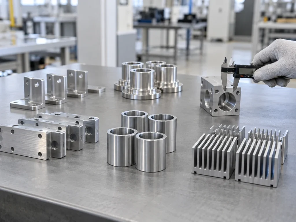
Aluminum hole position: one part, two end references
Imagine an ideal straight component with parallel ends. Its nominal length is 300 mm, and the nominal hole-center distance from end A is 40 mm. In this simplified one-dimensional example, the nominal distance from end B is 300 − 40 = 260 mm.
Now consider a fictional measured component whose length is 300.5 mm while its hole center remains 40 mm from end A. The corresponding distance from end B is 300.5 − 40 = 260.5 mm. The two observations describe the same component using different references.
| Reference in the example | Distance to the hole center |
|---|---|
| End A | 40 mm in both the nominal and fictional measured descriptions. |
| End B | 260 mm nominal; 260.5 mm for the fictional measured component. |
This arithmetic explains reference dependence. It does not establish an acceptable length, hole-location tolerance or machine accuracy. It also does not evaluate a three-dimensional hole axis. Actual acceptance requires the specified drawing and inspection method.
If the buyer checks from end A and the supplier checks only from end B, their reports may answer different questions. A helpful review first identifies the reference and requirement, then compares the results on that basis.
Five checks before the blank changes operations
1. Identify the reference features on the approved drawing
Read the drawing revision that applies to the finished component. Identify the dimensions, datum references and relevant notes for the hole or hole pattern. A rough sketch sent with a cut list may not contain enough information to define the finished feature.
In geometric tolerancing, a datum is an ideal reference established from designated real part features. The actual surface or hole used to establish it is a datum feature. Several datums can form a reference system. KEYENCE’s datum overview explains these basic terms.
The process stop or fixture contact should be reviewed in relation to that drawing scheme. Do not assume that the most convenient loading edge automatically becomes the design reference. Ask the responsible drawing and process reviewers to resolve any mismatch.
2. Confirm which end and which profile face are being carried forward
Define end A and end B consistently in the drawing, cut list and process handover. For an asymmetric extrusion, identify the relevant face or side as well. A part that looks similar after turning can still present a different face to the next operation.
Use an agreed orientation sketch and part identification method. Check mirrored or paired components against their own drawings. A left-hand part and a right-hand part may need separate identities even when their overall lengths match.
Our finished-length datum guide helps clarify the cutting reference. The cut-list revision guide helps keep the approved part and document identities aligned.
3. Separate hole size from hole position
State whether the feature is a through hole, blind hole, threaded hole, slot or another specified geometry. Then identify its required size and location controls. Measuring a diameter alone leaves the location question open.

Where the drawing uses geometric position, keep the complete feature control frame and its datum references in the review. Where it uses directly toleranced coordinates, follow that approved dimensioning scheme. Do not replace one with an informal conversion during a purchasing conversation.
A coordinate result can be useful information without constituting the complete required geometric evaluation. Modifiers, pattern relationships, datum precedence and the applicable drawing standard need competent interpretation when they are present. Include the full drawing rather than sending only an isolated number.
4. Review the final condition of any cut reference surface
If an end surface participates in locating the hole, clarify its required state when the next operation establishes the reference. Ask whether the approved route uses the saw-cut end directly or a surface produced by another operation.
Check the related requirements for that end. Its form, orientation and edge condition can need separate review. The cut-end flatness guide explains the surface-form question; the finished-part drawing determines which requirement actually applies.
Do not add a finishing operation by assumption. Record the proposed route and have the responsible team confirm how it delivers the required feature relationships. The same principle applies when the part is coated or otherwise finished after machining.
5. Keep the reference scheme visible in the inspection plan
Agree how the finished hole or pattern will be evaluated. Ask the inspection reviewer to identify the reference establishment, method, relevant feature coverage and reporting format. For a bore, the requirement may involve more than a center observed at one opening.
KEYENCE’s position measurement guide describes evaluation relative to datums and gives examples using a dedicated gauge or coordinate measuring machine. These are method examples; the suitable approach depends on the actual drawing and part.
A photograph of a probe near a hole cannot show the complete reference setup or acceptance decision. Request the linked result and method description. A reported pass needs to correspond to the characteristic that the buyer asked to accept.
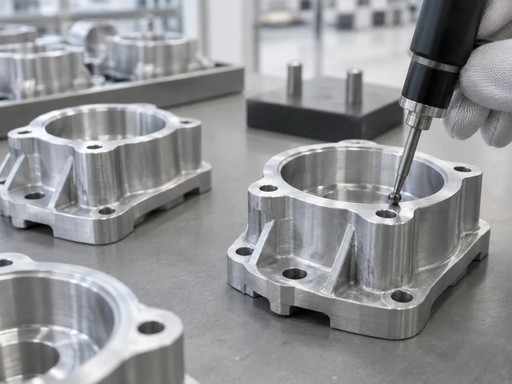
What the inspection report should answer
Keep the report easy to follow. Start with the part number, drawing revision, sample identity and inspection stage. Then make the inspected feature and its reference scheme traceable to the drawing.
- Which feature? Identify the individual hole, slot or pattern.
- Which requirement? Record the relevant size or location characteristic, units and limits.
- Which references? Identify the drawing’s reference features and the agreed evaluation basis.
- Which condition? State the finishing stage and relevant holding condition.
- Which result? Link the reported value and acceptance decision to the identified sample.
If a report covers only diameter, record that scope clearly and request the missing location evidence where the drawing requires it. If the drawing revision changed, review whether the report still answers the current requirement before reusing it.
For the wider route decision, see aluminum cutting and drilling process choices. That guide discusses the sequence of operations; this article focuses on maintaining the required feature references through that sequence.
A useful supplier request
Send the complete finished-part drawing, profile geometry, relevant cut list and proposed operation sequence. Highlight the holes or pattern that affect assembly. Identify the end or face references using the drawing’s own labels.
A concise request could read: “Please review the highlighted hole pattern on this drawing revision. Confirm the proposed cutting and machining references, identify the required final part condition, and propose the inspection evidence for the specified hole size and location.”
Include the batch mix and any paired-part identities. Ask the supplier to list unresolved drawing or route questions before the trial. Send those materials through the JiurunCut drawing review contact page to frame the cutting discussion.
Buyer questions about aluminum hole position
Does correct cut length guarantee correct hole position?
No. Length and hole location are separate characteristics. The finished component must meet each applicable drawing requirement using the agreed references.
Can I check from the opposite end because it is easier?
Confirm that the method answers the approved requirement. The simplified example shows that changing the end reference can change the distance being evaluated.
Does a good hole diameter prove assembly alignment?
No. Review location, orientation and the relevant mating-part requirements as specified. A diameter result alone does not establish the complete feature relationship.