
Digital caliper resolution tells you the display step. It does not, by itself, establish measurement accuracy or whether an aluminum part meets its drawing. Review the instrument specification, the contact method and the acceptance rule before using readings to approve a cutting trial.
A display that changes in 0.01 mm steps can show small differences. That fact alone does not demonstrate a 0.01 mm measurement error, a 0.01 mm uncertainty or a saw capable of holding that tolerance.
Start with three separate records
- The drawing defines the part requirement.
- The instrument documentation describes the tool.
- The inspection procedure explains how the result supports a decision.
On this page
1. Read digital caliper resolution as a display property
Check the stated display increment and the selected unit. In an assumed metric example, a 0.01 mm increment gives displayed values such as 100.00, 100.01 and 100.02 mm. The digits describe the indication available to the operator.
The BIPM vocabulary entry for display resolution concerns the smallest distinguishable displayed change. Keep that idea separate from a claim about how close a measurement is to the dimension being measured.
A finer display can help make readings easier to compare. It cannot resolve an unclear datum, an unsuitable contact position or an instrument operating outside its documented conditions. More decimal places do not repair those problems.
When recording results, retain the actual unit and reported indication. Avoid adding extra decimal places that the method did not provide. If data are exported into a spreadsheet, check that unit labels and original readings remain recognizable.
2. Identify the exact instrument and its documented limits
Ask for the tool model, identification number, measuring range and relevant specification. A general description such as digital caliper is insufficient when the trial record must be reviewed later. The actual tool needs to be identifiable.
Mitutoyo’s Digimatic caliper brochure lists resolution separately from maximum permissible error, with error entries depending on the model and measurement category. This manufacturer example shows why a display increment should not be substituted for the applicable error specification.
Use the documentation for the instrument actually being used. Confirm which specification applies to the feature and contact arrangement. Outside dimensions, inside dimensions and depth measurements can require different consideration; a single number copied from a catalog may omit its conditions.
The BIPM accuracy entry describes closeness to the true quantity value and treats accuracy as a qualitative concept. In a purchase discussion, identify what a numerical accuracy claim actually means and which documented limits support it.
Retain applicable calibration information with the tool record. A display showing zero after its jaws are closed does not establish the instrument’s behavior throughout the range used for the job. A quick operating check and calibration answer different questions.
3. Define how the jaws contact the aluminum feature
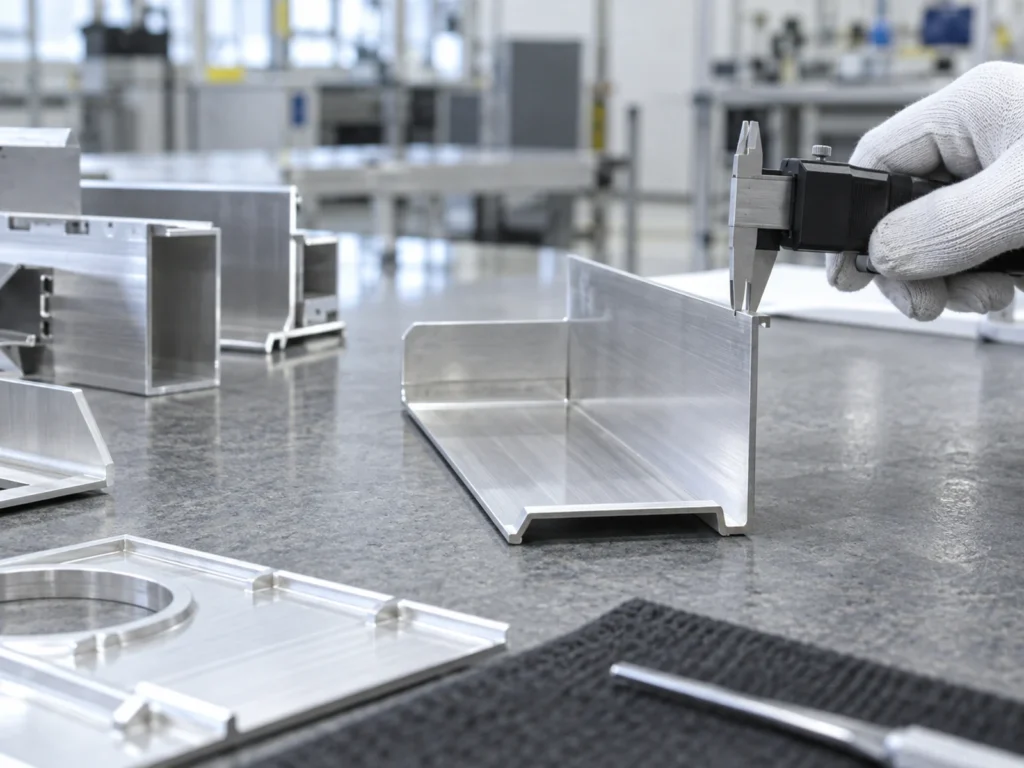
Name the dimension before choosing the instrument. A section width, a wall feature, a finished cut length and a miter long point are different measurement tasks. Write down the surfaces or points that define the intended result.
Then describe how the part is supported, where the jaws contact it and which preparation state applies. If one person measures a finished, deburred edge and another measures an as-cut edge with a burr, their readings may address different conditions.
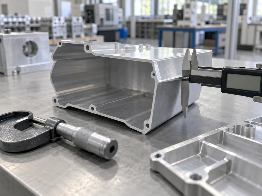
Thin or flexible features deserve a method review. Contact position and force can affect the part being observed. Use a procedure suitable for the feature rather than assuming that every surface visible in a photograph can be measured reliably in the same way.
Try representative parts with the intended operator and equipment. Keep any repeated readings associated with the same measurement task. If the setup changes, record that change instead of mixing different methods into one unexplained list.
For longer members, assess range, access and support before specifying a hand caliper. See the finished-length datum guide for defining the dimension and the temperature review for separating physical expansion from other measurement effects.
4. Connect the measurement result to the drawing requirement
The part tolerance comes from the agreed drawing or specification. The inspection method must support that requirement. A tool’s display increment neither sets the permitted part variation nor creates a new acceptance limit.
The BIPM uncertainty entry relates uncertainty to the spread of values attributed to the quantity being measured using available information. It can include several components, rather than only the visible fluctuation in repeated readings.
Agree how uncertainty and results near a limit will be handled. Keep the decision rule in the inspection plan. If the method is not yet suitable for a critical dimension, record the issue and arrange an appropriate review before declaring the sample accepted.
Compare numerical results only after the measurement definition is clear. The drawing tolerance examples explain limits and tolerance ranges. They do not assign a universal instrument selection ratio or a machine performance rating.
What four displayed readings actually show
Suppose a planned check uses a display increment of 0.01 mm. Four invented readings of the same feature are 100.00, 100.01, 100.00 and 100.01 mm. These values illustrate how to describe a small set of indications.
- Lowest displayed value: 100.00 mm.
- Highest displayed value: 100.01 mm.
- Observed displayed range: 100.01 − 100.00 = 0.01 mm.
The 0.01 mm range describes these four readings. It does not reveal the true dimension, establish the full measurement uncertainty or prove a production process capability. A stable indication can still be affected by a shared bias or a poorly defined contact method.
These are assumed teaching values, not JiurunCut test results. No acceptance conclusion follows without a drawing requirement and a suitable, agreed measurement procedure. Retain the readings and the conditions rather than replacing them with a claim that the machine is accurate to 0.01 mm.
Prepare a brief that another reviewer can follow
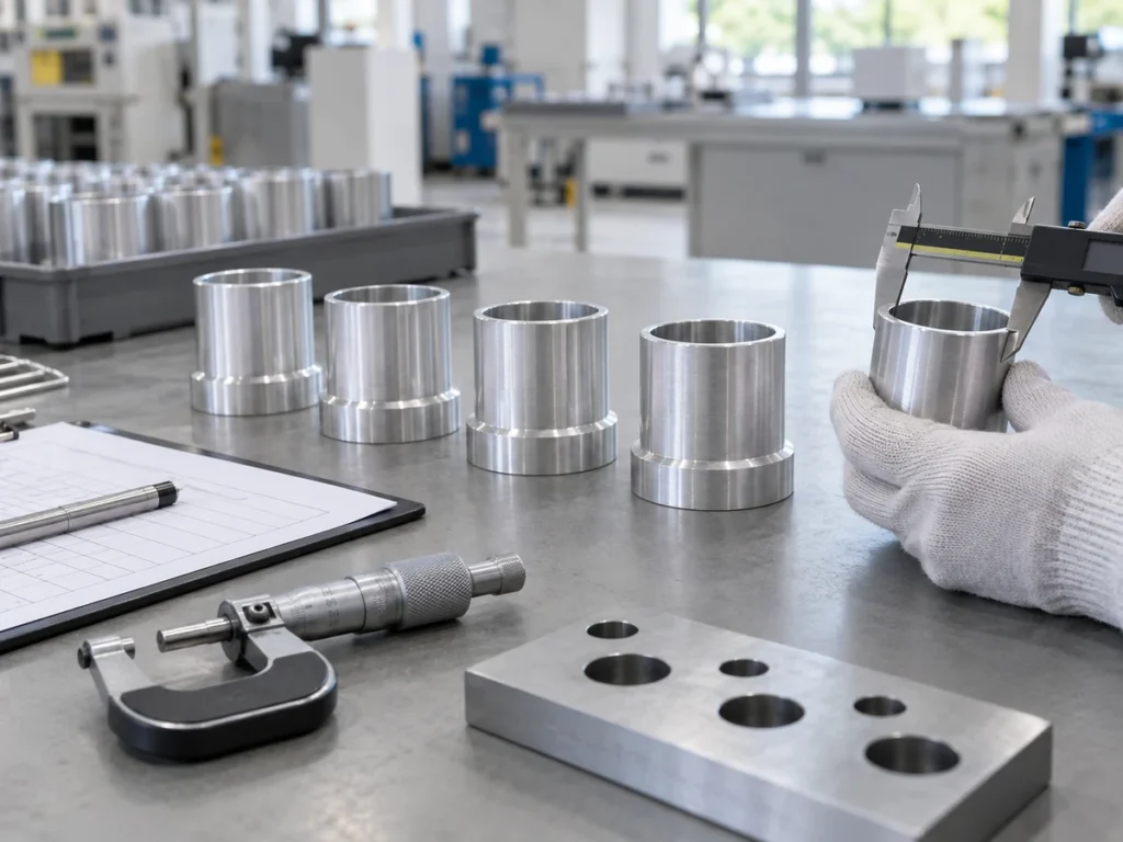
Before a supplier cutting trial, bring the drawing revision, feature identifier, relevant limits and representative sample requirements into one record. Attach the instrument identity and the proposed measurement procedure.
For each result, retain the sample identity, unit, operator and relevant conditions. Identify which readings were repeated on the same sample and which came from different parts. That distinction helps prevent a measurement check from being mistaken for a batch study.
Finish with a clear status: method agreed, review required or evidence still missing. If you need help planning a factory acceptance check, define the required evidence before the trial starts. Send JiurunCut the drawing and inspection brief to discuss a representative cutting review.
Common questions
Does a 0.01 mm display mean ±0.01 mm accuracy?
No. Display increment and an applicable instrument error specification are different properties. Identify the exact model, measurement category and stated conditions before discussing numerical performance.
Are identical repeated readings enough to approve a part?
No. They describe the observed indications under that check. Acceptance also requires the correct feature definition, suitable method, relevant requirement and agreed decision rule.
Should every aluminum cutting trial use the same caliper?
Choose equipment for the feature and required decision. Range, access, contact geometry and the documented measurement method matter. Keep the selected tool identifiable in the trial record.
Can digital caliper resolution prove a saw’s tolerance?
No. A saw performance conclusion needs an appropriate trial and measurement plan. The display step alone does not establish the machine’s error, variation or ability to meet a drawing.