
For conveyor side rail cutting, define the guide profile and the finished member before choosing equipment. Show its orientation, end joints, bracket interfaces and required quantity. Separate straight cut-to-length members from rails that need forming or another operation.
A cutting inquiry should explain what the saw must deliver to the next process. The final conveyor’s guiding, load and operational requirements remain part of its approved design and assembly review.
Start with these three distinctions
- A product guide rail and a structural conveyor frame member may have different jobs.
- A finished rail dimension and the assembled conveyor route are different drawing inputs.
- Cutting a straight blank does not establish the forming process for a curved rail.
On this page
1. Identify the member in the conveyor system
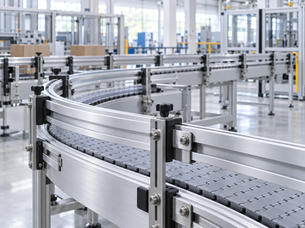
The name “side rail” can describe a guide beside the conveyed product or a member of the conveyor structure. Give the component a drawing number and explain its function. A request for a generic aluminum rail leaves too much uncertainty about the required section.
mk Technology Group describes application profiles for conveyor frames and side rails, among other functions. That product context shows why the specific profile matters. It does not mean that all these profiles are interchangeable or cut with the same arrangement.
Provide the supplied material designation and finish, the section drawing and the member’s intended position. If the guide includes a separate wear strip or another contact component, identify what is included in the cutting scope and what is fitted later.
2. Mark orientation and bracket interfaces
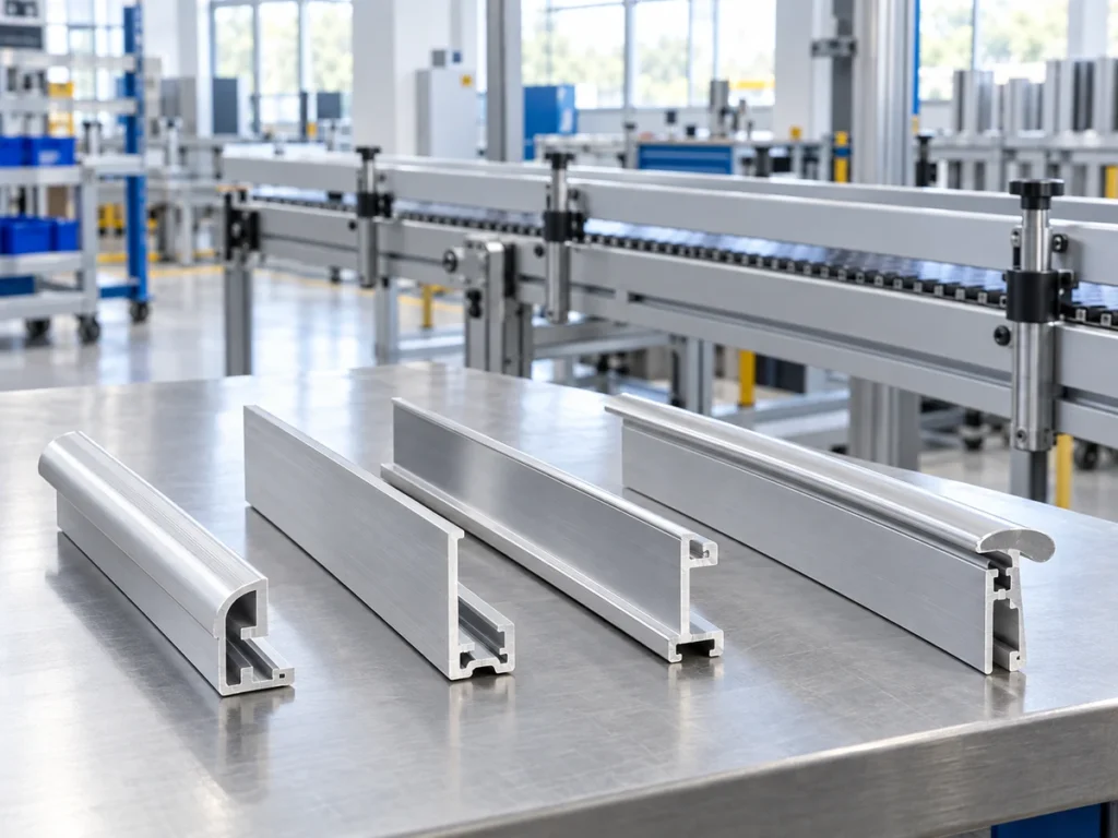
Show the profile in its installed orientation, then identify the faces and slots relevant to locating and holding it during the proposed cutting process. Keep the product-facing surface clearly marked so handling questions refer to the intended face.
Send the bracket or connector details that affect the finished member. A slot that accepts an attachment is an interface requirement, not just a decorative feature. Confirm which faces and end conditions the later assembly uses.
Similar overall width and height do not prove that two sections have matching slots, lips or wall arrangements. If you change the profile supplier or section revision, ask the responsible design team to confirm compatibility before carrying the old cut list into the new job.
List any later holes, end machining or fitted parts separately. The saw may produce a blank for those operations rather than a fully finished rail. Specify the required blank length and any drawing-based allowance without silently adding another process to the cutting quotation.
3. Define how the ends meet
For each member, show the required end direction and the reference used for finished length. Mark square ends, angled ends or a special end condition explicitly. If a rail is mirrored on the opposite side of a conveyor, retain its identity in the drawing and cut list.
A joint photograph helps explain the arrangement, but it does not give the permitted gap, step or length variation. Obtain those requirements from the approved design. Do not infer an allowable joint condition from a visually smooth transition.
Review the rail ends together with the intended connector or adjoining member. Measure the individual drawing dimensions as well as checking the representative joint. An assembled fit can provide useful evidence without replacing the specified component checks.
4. Separate straight and curved work
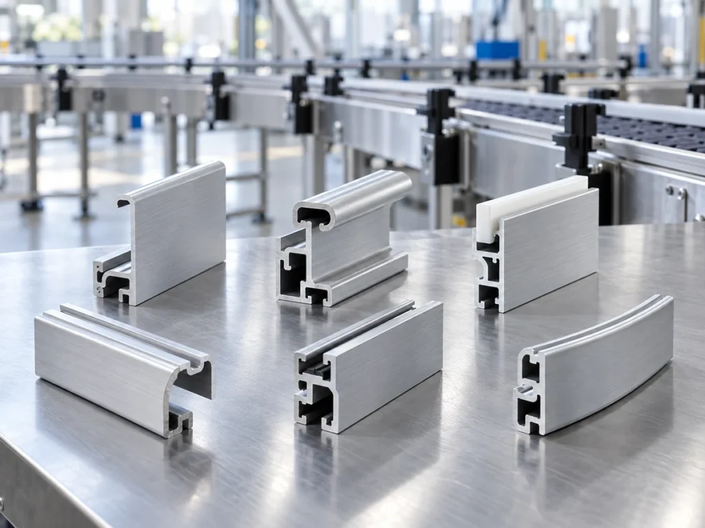
A conveyor route may contain straight guides, formed curves and transition members. Identify each family and the operation sequence required by its approved drawing. A general request to “cut rails for this route” does not explain which process creates the curve.
If a rail is cut as a blank before forming, obtain the blank requirement from the responsible forming process. If it is trimmed after forming, explain the formed shape and required end references to the cutting supplier. These are different workpieces and setup reviews.
Do not assume that the developed blank length equals a straight-line distance between two points on the installed route. Use the approved process drawing for the actual member. The cutting review should retain that dimension and its revision.
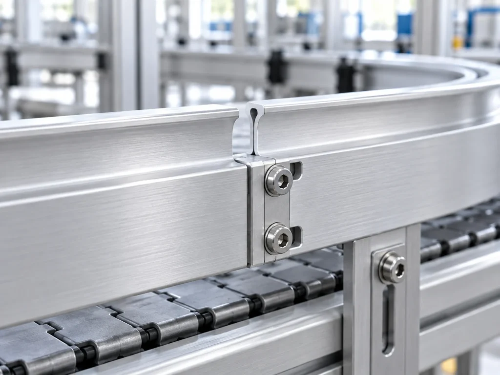
Keep transitions between straight and curved members in the assembly review. Record orientation, adjoining components and the stated joint requirements. A successful cut on a straight sample does not establish how a formed member will be supported or trimmed.
5. Plan quantities and the handoff
Here is an invented counting example. Six straight conveyor modules each require two identical guide members, giving 6 × 2 = 12 rails. Four additional replacement rails of the same drawing bring the total requirement to 16 accepted rails.
The count defines the delivery requirement. It does not predict raw-stock yield, production time or an appropriate machine. Those depend on the actual finished lengths, cut sequence, supplied stock and proposed cutting arrangement.
- Production kits: six identified pairs, two rails per pair.
- Replacement members: four separately identified rails.
- Total accepted quantity: twelve plus four, or sixteen.
Label the pairs and the replacement group so receiving staff can account for both. If some members have a different orientation, length or revision, give them separate identities and quantities rather than grouping them under the same total.
For the stock calculation, prepare the real sequence and refer to the kerf and stock-length guide for its clearly defined straight-cut example. Include any material and holding requirements confirmed for your own setup.
At handoff, retain the drawing revision, part identity, material lot and inspection status. Use suitable approved handling and packaging for the profile and finish. The cut-part packaging guide explains how to separate released pieces from material still held for review.
Review a representative sample before the batch
Use the actual guide section and representative supplied condition. Ask the supplier to identify the proposed machine configuration and approved support arrangement. Include any short members, mirrored ends or formed pieces that make the task different from a simple straight rail.
- Dimension check: verify the required finished length and end references.
- Surface check: review the identified product-facing and visible surfaces.
- Interface check: review the intended brackets, connectors and adjoining members.
- Handoff check: confirm that part identity and release status remain clear after collection.
Document what the trial covers and which later operations remain. Conveyor operation, guiding performance and structural requirements need the applicable system-level review. A cutting sample evaluates the component checks actually performed.
Common questions
Can one conveyor side rail cutting setup cover every section?
Ask the supplier to review each actual profile family and finished-part requirement. Similar-looking rails may have different contact faces or interfaces. Keep the approved configuration and any changeover requirements connected to the relevant drawing.
Should a curved rail use the same length field as a straight rail?
Use the dimension defined for that component and its process route. A formed or preforming blank needs the appropriate drawing reference. Do not substitute an installed route distance for the required member dimension.
Does a clean rail joint prove conveyor performance?
No. It is one observation about a particular assembly. Perform the component and system checks required by the approved design. A visual joint review does not establish guiding, load capacity or operating performance.
Prepare a clear rail-cutting inquiry
Send JiurunCut the guide section, installed orientation, member drawings, end joints, straight or formed workpieces and batch quantities. We can discuss the cutting task and a representative sample review for your rail families.