
Aluminum cutting kerf is the length of material removed by a saw cut. A stock plan must allow for that removal as well as finished parts, front-end preparation and the material left at the end. Count each item once, then check that the lengths add back to the original stock.
This guide works through one straight-cut example. It shows why dividing stock length by part length alone can overstate the available pieces. All dimensions below are invented planning inputs, not a JiurunCut machine specification or a cutting-test result.
Follow the stock calculation
Keep aluminum cutting kerf separate from other allowances
The finished-part length describes what you need to deliver. Kerf describes material removed between the resulting pieces. Front trim prepares a stock end, while the end reserve belongs to the reviewed feeding and holding arrangement.
These inputs answer different questions. Combining them into one unexplained “waste allowance” makes it difficult to check a calculation or compare two offers.
Also distinguish the blade’s cutting width from its body thickness. For example, LEUCO’s published data for an aluminum-profile saw blade lists these as separate properties. This is a terminology reference, not a recommendation to fit that blade to your machine.
Have the supplier confirm the planning kerf for the approved blade and setup. Keep the source of that input on the job record. A value copied from another blade or an old spreadsheet may not describe the proposed configuration.
Define the sequence before using a formula
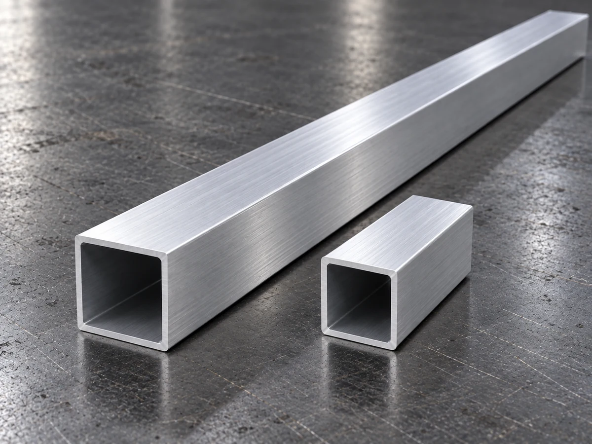
For this example, the approved plan first removes a front offcut and its associated saw kerf. It then produces identical straight-cut parts, with one separating cut for every finished piece. The remaining stock stays as one tail.
The example does not use the original stock end as the final finished-part face. It includes no later end trim, angled-cut geometry or mixed-length nesting. Those conditions would need a different cut count or allowance.
The invented inputs
| Planning input | Example |
|---|---|
| Original stock | 6,000 mm |
| Front offcut | 20 mm |
| Front preparation kerf | 3 mm |
| Finished part | 500 mm |
| Kerf per production cut | 3 mm |
| End reserve | 120 mm |
The 120 mm reserve is an assumed planning boundary. It is not a minimum tail length for any machine. Ask the supplier to confirm the required reserve for the actual profile, fixture, feeding method and offered configuration.
Use a consistent unit throughout the calculation. Here every length is in millimeters. For a real order, also review the supplied stock-length specification and what happens when individual lengths differ from the planning assumption.
Calculate how many whole pieces fit
1. Find the prepared stock length
Remove both the front offcut and the material lost in its preparation cut:
6,000 − 20 − 3 = 5,977 mm.
This is the stock available after front preparation. The 3 mm front kerf is already accounted for, so it must not appear again among the production cuts.
2. Protect the assumed end reserve
Subtract the 120 mm planning reserve from that prepared length:
5,977 − 120 = 5,857 mm.
The remaining 5,857 mm is the length budget for finished parts and their separating kerfs under the stated sequence.
3. Include aluminum cutting kerf for every piece
Each 500 mm part uses 503 mm of that budget: 500 mm delivered as the part, plus 3 mm removed by its separating cut.
5,857 ÷ 503 = 11.64; round down to 11 whole pieces.
A fraction of a part cannot fulfill the order. Twelve pieces would require 6,036 mm for parts and production kerfs alone. Adding the assumed 120 mm reserve would require 6,156 mm, which exceeds the prepared stock length.
Check where the full 6,000 mm goes
Eleven finished parts total 5,500 mm. Their eleven production cuts remove 33 mm. Subtracting both from 5,977 mm leaves a 444 mm tail.
The physical length balance is:
| Length destination | Example |
|---|---|
| Front offcut | 20 mm |
| Front kerf | 3 mm |
| 11 finished parts | 5,500 mm |
| 11 production kerfs | 33 mm |
| Remaining tail | 444 mm |
| Total original stock | 6,000 mm |
The 444 mm tail already contains the 120 mm reserve. Its other 324 mm is unused length under this particular plan. Do not add another 120 mm to the physical balance; that would count the reserve twice.
Whether a remaining length can serve another job depends on its identity, usable condition and the reviewed process. Keep reusable stock separate from scrap in the record. The tail-waste planning guide explains the questions to take into that review.
Does every order have one kerf per finished piece?
No. The number of saw cuts follows the actual sequence. A usable existing end, additional end preparation or a different part arrangement can change the count.
For a mixed order, list the total finished lengths and the kerf for each planned cut. Then include front preparation and the required remaining length. Check each proposed stock pattern rather than applying this identical-part example to the entire order.
Angled parts also need clearly defined measurement references. Do not treat a straight-cut length formula as an angle-cut nesting method. Use the controlled drawing and the supplier’s reviewed cutting plan.
Should kerf be added to the controller’s part-length setting?
Keep the drawing’s finished-part dimension unchanged. Confirm how the approved controller program handles compensation before entering production values. Some programs may already account for the configured cutting width; adding an allowance again could duplicate it.
This article explains stock planning. It does not replace the machine manufacturer’s programming instructions or the site’s approved setup procedure.
Bring a checkable stock plan to the supplier
Send the profile drawing, supplied stock-length information, finished lengths and quantities. Show the intended cut sequence and identify every assumed input, including aluminum cutting kerf, front trim and the end reserve.
Ask which inputs the offered configuration can confirm and which need a representative trial. Record the approved blade/setup reference and the resulting part checks so the plan can be reviewed when the job changes.
For the order sheet itself, use the aluminum cutting-list guide. It helps connect each row to a part and drawing revision; this calculation then checks how those rows consume stock.
JiurunCut can review your aluminum cutting kerf assumptions and stock plan with the proposed equipment configuration. Review My Stock-Length Plan →
Reference and example scope
Terminology source: LEUCO, NF-Chop Saw Blades HW TR-F, article 188388. All worked dimensions are invented. Images are illustrative and do not document the calculated job or a machine test.