
A control cabinet frame extrusion saw trial should begin with the assembled frame. The cutting list may look simple: uprights, crossmembers and a set of matching lengths. In assembly, those lengths become a door opening, panel edges and connector seats. A saw trial for these extrusions should therefore answer a purchasing question: can the proposed machine and workholding method make a repeatable set of assembly-ready members from the buyer’s actual profile family? It should not stop at a tidy photograph of one cut end.
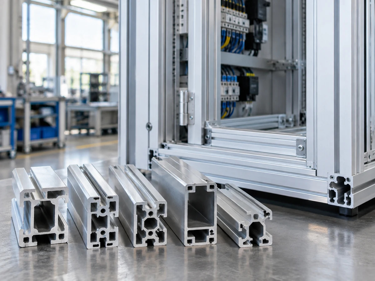
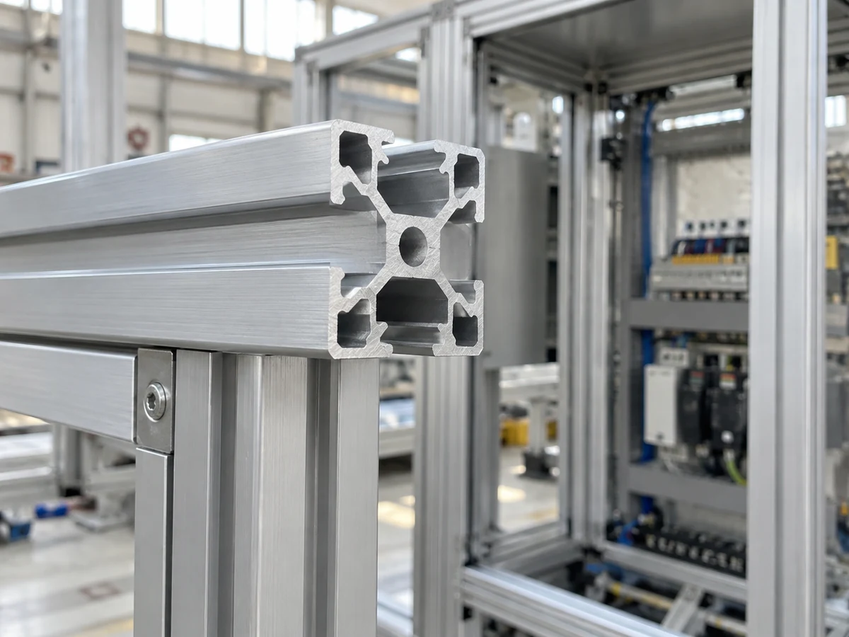
This guide gives a buyer a practical trial sequence. The frame images below illustrate types of section, stock and corner connection. They are not records of a JiurunCut customer job or proof that a named machine achieved the fit described here. Use your released drawings, actual extrusion and hardware to establish acceptance.
Control cabinet frame extrusion saw trial: start with assembly
For a cabinet made from aluminum extrusions, the same cut length can affect several interfaces: the overall frame envelope, squareness of a corner, panel capture and the clearance around a door or service opening. Ask the cabinet designer which dimensions are controlled by the extrusion cut and which will be set later by connectors, machining, adjustment or assembly. A saw cannot be judged against a final cabinet dimension without that tolerance chain.
Choose one representative cabinet module and list every member that the saw will cut. Mark the section identifier, finish, stock length, required cut length, end orientation, quantity per frame and the next operation. Add the mating bracket or fastener and the panel or door interface that will expose an error. Keep production drawings and revision numbers with the trial order so that a later change of connector does not silently change the acceptance rule.

Select samples that expose different cutting risks
A single easy profile is a poor proxy for a mixed cabinet package. Include the longest upright, a short crossmember that challenges the stop or feeding sequence, a thin-walled or open section, and any profile with a different bearing surface in the clamp. If visible anodized or coated faces matter, use finished material. If a gasket channel, T-slot or panel groove sits close to the end, make that section part of the trial as well.
Before running the saw, note the stock condition. Bow, twist, variable wall thickness, protective film and existing surface marks can change both support and the appearance of the sample. Separate incoming-stock defects from cut-induced defects in the inspection record. Do not promise that one test of straight, clean stock predicts every future extrusion lot.
Establish a datum and a clamp plan for every section
Write down which face touches the fence, which face rests on the table and how the extrusion is oriented at each cut. A broad nominal dimension alone is not enough when slots, lips and hollow chambers make the actual contact area small. The operator should be able to load the section the same way each time without resting it on a fragile flange or marring the face that remains visible on the cabinet.
For hollow or asymmetric members, inspect the clamp pad contact and any sacrificial support before production. A pad that bridges a slot may push the profile out of position; excessive force may distort a thin wall. A support that sits below a protruding lip can let the profile roll as the blade enters. Ask the supplier to show the intended fixture, not just a catalogue picture of a generic pneumatic clamp. Record any section-specific jaw, stop, insert or operator setup as part of the proposed configuration and quote.
Make the length datum explicit. Is it a physical stop, a feed datum, or an end previously cut square? For a two-end member, agree whether the first end is a cleanup cut and whether the final length is measured between the retained cut faces. When a drawing calls out an assembled opening, determine the connector offsets first. Feeder positioning repeatability is not the same as finished-part length accuracy, and neither by itself proves door fit.
Inspect the end as a mating surface
Measure the retained length using the drawing’s method, then examine end squareness relative to the agreed datum. Check the side walls, lip edges, channels and coating around the cut for burrs, rollover, crush, scratches and chips trapped in grooves. Define the permitted deburring operation in advance. A sample that fits only after unquoted manual correction does not demonstrate the same production process as a clean off-saw member.
Use a short run of consecutive parts, not only the best specimen. Keep the first, middle and final members identifiable, and record setup changes. If a section must be rotated or a clamp pad swapped, repeat the relevant end and length check after that change. The result should show the process window the buyer would actually use, including scrap or rework decisions.
Prove the corner, door and panel interfaces separately
Build a small representative corner or rectangular module with the specified connectors. Check whether cut faces seat evenly, fastener access is available and the joint can be assembled without forcing a member into position. Compare the diagonal or squareness measurement with the buyer’s drawing method. A visually flush corner is useful evidence, but it cannot replace a stated dimensional acceptance test.
Next, install the intended panel strip or a gauge made to the panel’s controlled dimensions. Look for interference at the groove end and around corner hardware. If the frame carries a door, check the opening against the hinge and latch layout with the released door components or a fit gauge. Record whether the adjustment range, rather than a precise cut alone, produced the final fit. Do not claim a seal, ingress rating or electrical compliance from a saw trial; those are system-level questions under the cabinet maker’s design and test plan.
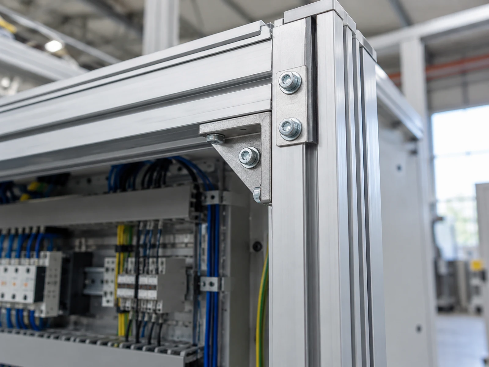
As an architecture example, item’s clamp-profile connector information describes framed panel elements and their connection concept. Its dimensions and hardware apply to item products, not to JiurunCut equipment or to your cabinet. The value here is the reminder to test the actual joint and panel interface. item’s sliding-door assembly instructions likewise show that cut frame members become a door assembly with corner fasteners and a panel; your own drawing defines the acceptance details.
Ask the supplier for a reproducible trial record
For each section, request the stock ID and condition, cut orientation, fixture setup, blade and process configuration, number of samples, measurement method and the result for each acceptance feature. Photograph the retained ends and any assembly gauge beside a part identifier. Note burr-removal time, clamp marks and chips in grooves when they affect downstream work. If a critical profile was omitted, label that gap rather than treating the tested section as proof for the whole family.
When comparing offers, price the complete route: material handling, stock support, cutting, deburring, cleaning, labeling and the changeover between sections. Ask which items are in the quoted machine, which are optional fixtures and which are buyer-supplied gauges. Keep a separate decision for throughput after the quality route works. A fast cut that produces manual fitting at every corner can make the cabinet cell slower overall.
A simple acceptance sheet for the buying decision
- Identity: drawing revision, profile/finish, connector and panel or door part used.
- Setup: datum face, orientation, clamp/support tooling, first-end and final-length method.
- Output: consecutive sample count, retained lengths, end squareness, burr/finish observations and rework.
- Assembly: corner seating, frame squareness, panel insertion, door opening and fastener access against the buyer’s gauges.
- Commercial scope: included fixtures, section changes, operator work and unresolved samples.
Sign off only the features actually measured. If a candidate passes the cut checks but fails a door interface, identify whether the cause is cutting, connector geometry, stock variation or assembly adjustment before changing machine requirements. That makes the next supplier trial focused and comparable.
Equipment footage: general example only
The following video is from Jiurun Machinery’s YouTube channel and shows general aluminum-saw equipment. It is not a control-cabinet frame trial, a particular machine configuration, a customer installation or evidence of the tolerances and fit discussed above. Use it to see equipment motion only; request a trial using your own profile, connector and acceptance drawing.
Video caption: general saw-equipment footage from Jiurun Machinery; it does not demonstrate this cabinet material, configuration, customer, cut quality or performance.
What to send JiurunCut
Send the extrusion cross-section drawings, stock lengths, cut list, finish requirements, mating connector drawings and the frame/door/panel acceptance method. State the expected section mix and changeovers. Contact JiurunCut with that package to discuss a representative cutting trial and the required workholding. For earlier-stage machine selection, see our control cabinet frame manufacturing guide and T-slot extrusion saw trial guide. Confirm the exact machine and fixture proposal against the approved test plan before ordering.