
For automatic miter cutting for LED aluminum profiles, check a complete corner with the specified connector and matched cover. The aluminum seam can look aligned while the cover sits unevenly or the connector does not fit correctly. Show the supplier these assembly requirements before choosing the cutting setup.
What to check before choosing the machine
- Keep the profile drawing, corner connector and cover references together.
- Check the features inside the joint as well as the visible seam.
- Agree on finished-part measurements and a complete-corner check using repeated cuts.
On this page
Bring the matched parts to the review
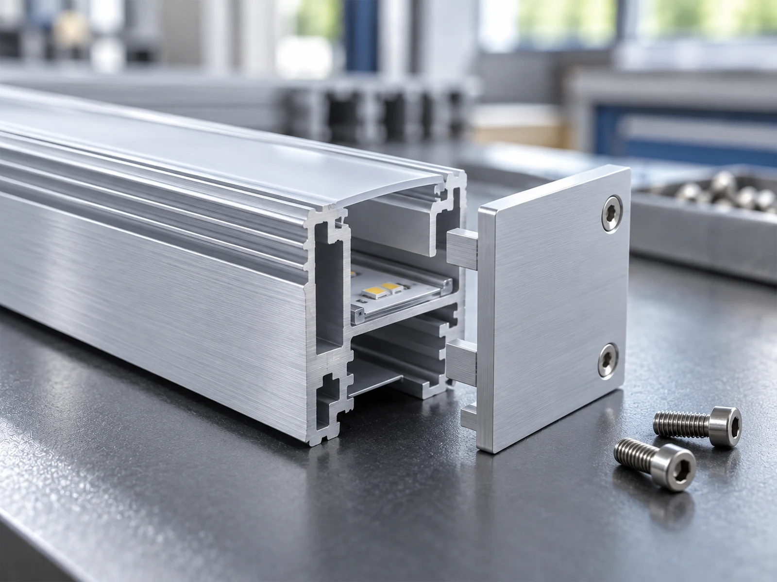
A miter cut is an angled end cut used to bring two members together at a corner. In a lighting assembly, that corner may also need an internal connector and a cover. A diffuser is a light-spreading cover. Its seating edges must match the profile chosen for the product.
Start with the profile cross-section, the shape seen at the cut end, and the corner drawing. Add the connector and cover references. Show whether the design uses separate covers, a corner accessory or another arrangement. Similar outside dimensions can hide different internal features.
Hydro’s LED profile overview describes features such as clips, screw channels and slide-in compartments, and connections to diffusers. These features make the actual cross-section important to the review.
Need a machine for your LED profile corners?
Send a profile or corner photo and tell JiurunCut what does not fit. Add the connector and cover details if you have them.
Define the ends and profile direction
Mark the end cuts and finished length on the drawing. State whether the length is measured at the outside point, inside point or another feature. A datum is the face or edge used as the measuring reference. Keep it consistent between cutting and inspection.
Show which way the cover opening faces and label any left- and right-hand pieces. Turning a profile with an uneven cross-section can change which internal features meet.
Ask the supplier to relate the drawing’s end angles to the proposed machine positions. Our finished-length datum guide explains measurement references in more detail.
Check connector channels and cover seats
A connector channel is the groove or space that receives the joining hardware. A cover seat is the edge or groove that locates the cover. Mark both on the cross-section, then check how they meet at the corner.
The KLUŚ ZM-90 connector page, for example, shows a lighting-section connection mounted to the profile with a lock and pressure screws. Bring the joining parts specified for your own design so their fit can be checked.
| Feature | Question for the part review |
|---|---|
| Aluminum end faces | Do the mating faces meet as required by the corner drawing? |
| Connector channels | Do the channels align so the specified connector can locate and be secured as intended? |
| Cover seats | Do the seating edges line up and allow the matched cover or corner accessory to fit as designed? |
| Internal space | Is the drawing-defined space for the lighting components and wiring preserved at the corner? |
| Visible surfaces | Does the assembled corner meet the agreed requirements for seams, alignment and surface marks? |
If the cover sits unevenly, record where it first catches or lifts. Keep that observation with the length and angle measurements. The cut end, profile direction, edge condition and component match can then be checked separately.
Review finish, support and clamping
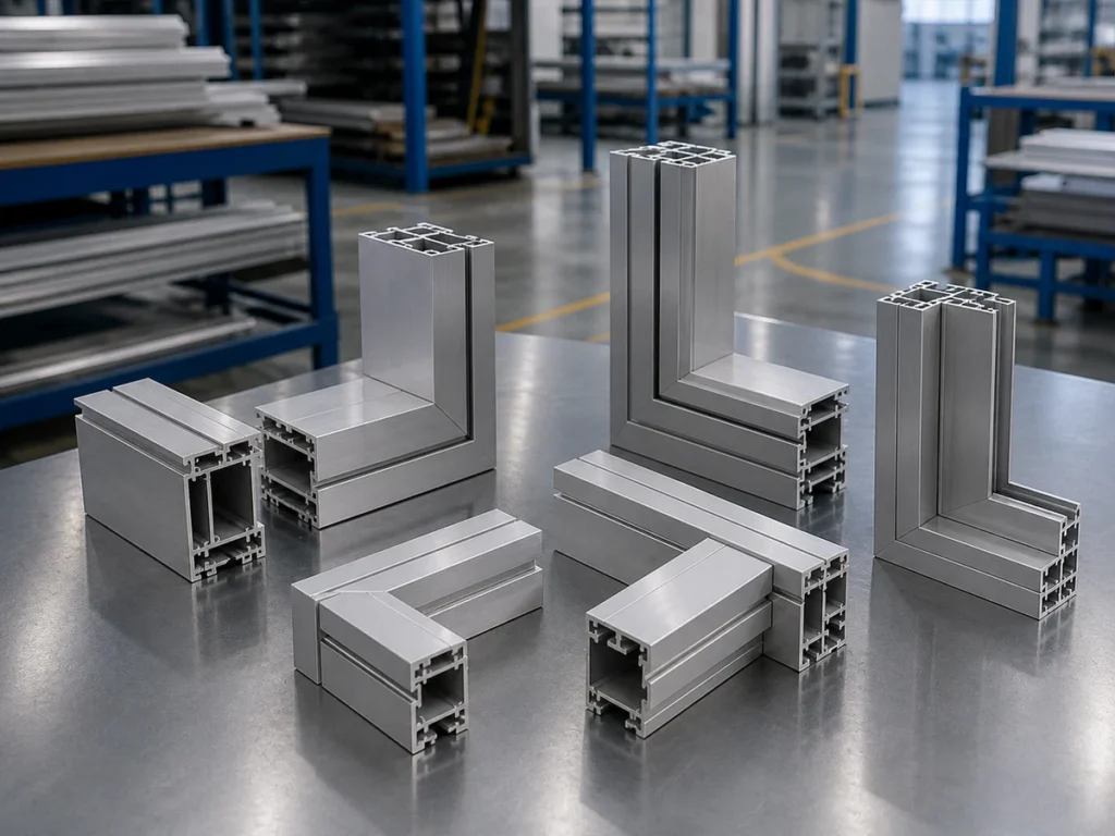
Tell the supplier whether the aluminum is bare or has a surface finish. Mark the visible faces and thin cover-seat edges. Include the wall thickness and normal stock lengths.
A fixture supports and holds the profile. Ask where it will contact the section and how it supports each required cut. Include the thin cover-seat edges and connector channels that need to retain their shape.
Agree the permitted surface marks and edge condition. Inspect after normal feeding, clamping and collection. If edge finishing or cleaning is needed before assembly, make clear who performs it and whether it is included in the offer.
Check repeated parts and complete corners
For an agreed sample trial, use the actual aluminum section and finish, normal end cuts and proposed handling arrangement. Include left- and right-hand pieces where needed.
Measure lengths and end angles against the drawing. Assemble representative corners with the specified connectors and covers. Check the fit, internal alignment and visible seam using the assembly requirements for those components.
Check a sequence of parts to see whether the result stays consistent. Agree the sample quantity and acceptance method with the supplier. Keep the drawing revision, profile and component references, setup details and results together.
Our sample-cutting checklist helps organize the wider trial record.
Have a corner fit issue to review?
Send the drawing or a clear photo showing where the connector or cover does not fit. Ask about a cutting trial using your parts.
Review the machine and quotation scope
The JR-550CNC-CORNER automatic multi-angle aluminum cutting machine is a JiurunCut option for review when angled aluminum parts recur in production. Send your LED profile and corner drawings to discuss the required cutting positions, support and handling.
Describe the lengths, angle changes and quantities in a normal batch. Ask which tasks the automatic cycle includes. Include part identification and collection when similar-looking pieces must remain matched.
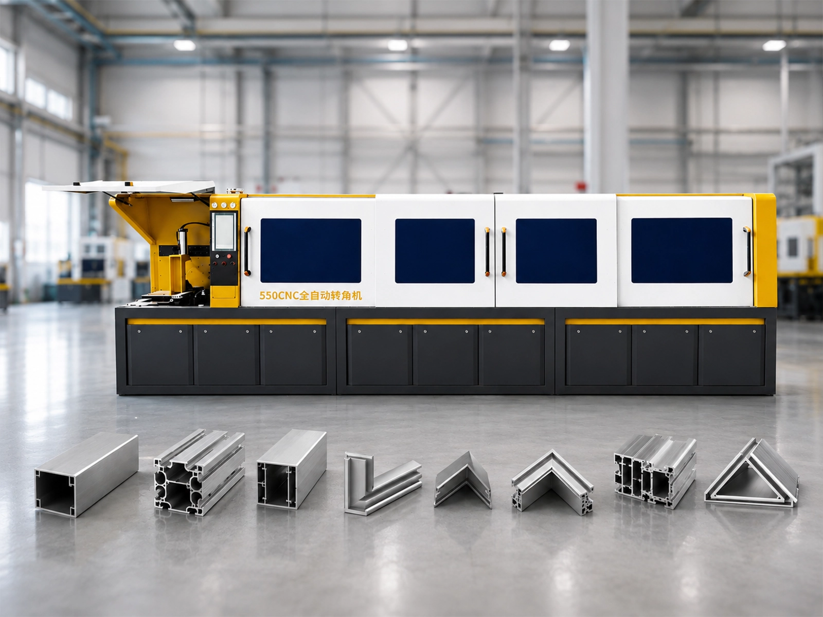
Watch: JR-550CNC Fully Automatic Angle Saw
Jiurun machinery channel’s general angle-saw demonstration. Use it to discuss the automatic cycle; your LED profile and complete-corner requirements need their own review.
Ask the quotation to identify the model, fixtures, stock supports, feeding and collection equipment, blade and chip collection. Clarify any later drilling or assembly work. Confirm installation, training, support and spare-parts arrangements for your location.
For the information needed at the saw-blank handoff, use our LED housing blank specification guide. For the broader automation buying decision, see how to choose an automatic multi-angle aluminum cutting machine.
Ask about an LED profile cutting configuration
Start with your profile or corner photo and what you want to improve. Add typical lengths, angles and quantities if known. We can clarify the remaining details with you.
Automatic miter cutting for LED aluminum profiles: buyer questions
What should a complete-corner sample include?
Use the drawing-defined aluminum pieces, the specified connector and the matched cover or corner accessory. Keep the measured length and angle results with observations of connector fit, cover seating and visible surfaces.
Can I start with a photo of the assembly?
Yes. Send a clear profile or corner photo and explain the cutting or fit problem. Add the drawing and component references as they become available so the final machine review uses the correct parts.
Does the aluminum cutting proposal include the diffuser?
Define the aluminum cutting scope and cover-preparation scope separately. The cover’s material, end requirements and preparation method need to be agreed before equipment suitability is confirmed.
Sources and scope
Hydro and KLUŚ provide the interface examples linked above. JiurunCut machine identity comes from its brochure and product page. Illustrations and the general saw video are not LED-part test evidence. This guide concerns aluminum cutting; cover preparation and electrical, optical and thermal verification need their own process. Specific part suitability remains to be confirmed.