
An aluminum tolerance stack describes how contributing dimensions combine to affect a defined assembly distance. Start with the actual endpoints and dimension path, then calculate the upper and lower limits using the correct signs. A single part’s cut-length tolerance is only one input.
The three examples below use fictional, one-dimensional geometry. They explain the arithmetic for buyers reviewing cut parts and assemblies. Their dimensions and limits are not recommended specifications or demonstrated JiurunCut machine performance.
Before calculating
- Define the finished distance and its two reference features.
- Identify every contributing dimension, direction and limit.
- Keep the calculated range separate from the assembly requirement.
On this page
Define the distance for the aluminum tolerance stack
Give the result a name, such as the distance between two assembly faces or a clearance between a member and a stop. State the measurement direction. A list of part lengths is not yet a dimension path.
Draw or describe which dimensions connect the first reference feature to the second. Identify which dimensions add to the result and which subtract. Include required joint offsets, overlaps or other contributors where the actual assembly model calls for them.
The SOLIDWORKS TolAnalyst overview describes a study using a selected measurement, an assembly sequence and assembly constraints before evaluating the results. The useful lesson for a buyer is to define the actual relationship between the parts. Software does not supply an approved assembly requirement merely because an analysis can be run.
Keep length references consistent. A mitered member’s long-point length may not equal the distance that contributes to the assembled frame. Use the miter-length explanation when checking how the part and assembly dimensions relate.
Use one unit throughout the calculation. Convert both nominal dimensions and their limits when necessary. The inch-to-millimeter drawing guide explains why rounding a converted nominal value is different from changing its tolerance.
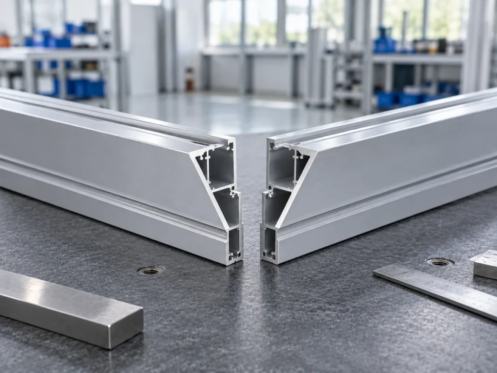
Example 1: two lengths that add
Assume a simple collinear model in which total distance T equals A plus B. There is no joint gap or overlap in this fictional model. The allowed input ranges are independently defined.
Let A be 100.0 mm with a symmetric ±0.2 mm limit and B be 200.0 mm with a symmetric ±0.3 mm limit. A ranges from 99.8 to 100.2 mm; B ranges from 199.7 to 200.3 mm.
The smallest total is 99.8 + 199.7 = 299.5 mm. The largest is 100.2 + 200.3 = 300.5 mm. The nominal total is 300.0 mm, with a calculated worst-case range of 300.0 ±0.5 mm under this model.
| Fictional input or result | Allowed or calculated range |
|---|---|
| A: 100.0 ±0.2 mm | 99.8 to 100.2 mm |
| B: 200.0 ±0.3 mm | 199.7 to 200.3 mm |
| T = A + B | 299.5 to 300.5 mm |
The ±0.5 mm result is calculated from the stated inputs. It is not automatically the permitted tolerance of an actual assembly. Compare the calculated range with the responsible drawing’s assembly requirement.
Worst-case arithmetic uses the relevant extreme limits. It does not predict how often real parts will lie near those extremes. A statistical analysis is a different study with additional assumptions and evidence.
Example 2: a gap that subtracts one dimension
Now assume a different fictional model: gap G equals opening D minus occupied length L. The dimensions refer to the same line and the defined faces. Other offsets and contributors are absent only because this simple example explicitly excludes them.
Let D be 500.0 ±0.4 mm and L be 100.0 ±0.2 mm. D ranges from 499.6 to 500.4 mm. L ranges from 99.8 to 100.2 mm.
The smallest gap uses the smallest opening and the largest occupied length: 499.6 − 100.2 = 399.4 mm. The largest gap uses the largest opening and the smallest occupied length: 500.4 − 99.8 = 400.6 mm.
The nominal gap is 400.0 mm and the calculated worst-case range is 400.0 ±0.6 mm. Subtracting the nominal dimensions does not mean subtracting their tolerance magnitudes. The two extremes that reduce the gap act together.
This is a length example, not a recommended clearance. A real fit analysis needs the actual reference features, contributors and assembly requirement. Do not use its gap value or limits as a design rule for a connector, guard or machine frame.
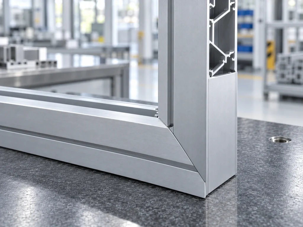
Example 3: two lengths with one-sided limits
Return to a simple sum T = A + B. This time each fictional length is 25.0 mm with an allowed deviation of +0.1 mm and −0.0 mm. Each input ranges from 25.0 to 25.1 mm.
The total therefore ranges from 50.0 to 50.2 mm. Relative to the 50.0 mm nominal sum, its calculated limits are +0.2 mm and −0.0 mm.
Writing the result as 50.0 ±0.2 mm would allow a lower value of 49.8 mm, which is outside this model’s calculated range. A symmetric notation cannot replace a one-sided range without changing its meaning.
The same interval can be expressed around its midpoint as 50.1 ±0.1 mm, but that midpoint is not the original nominal sum. Preserve the drawing’s nominal value and limit notation in the production requirement unless the responsible design process approves a change.
These are illustrative interval calculations. They are not instructions to alter drawing limits, assume parts are centered in their ranges or change a machine’s cut-length compensation.
Review the real assembly before assigning part requirements
Check that every input matches the current drawing and the intended feature. Autodesk’s tolerance-stackup documentation emphasizes selecting the relevant features, dimension direction and assembly relationships, then checking the contributing dimensions against the actual dimensioning scheme. It also describes offsets between parts as separate inputs.
The three examples above intentionally exclude angular, geometric, contact and deformation effects. Actual assemblies may need a more complete analysis. A scalar length sum is not a substitute for the engineering review of those effects.
Keep the distinction between specified limits and observed production results. A drawing tolerance does not demonstrate process capability, and an assumed statistical distribution is not created by entering a nominal dimension.
Use the part-tolerance guide to communicate each cutting requirement. Keep the approved drawing and cut-list revisions with the analysis so an altered member or joint can be reviewed.
For a machine quotation, identify which part dimensions need supplier evidence. Describe the assembly requirement separately. This lets the supplier discuss the actual cutting task without converting a simple example into a machine-accuracy promise.
Questions about an aluminum tolerance stack
Do part tolerances always add?
For a simple independent one-dimensional worst-case model, the contributing interval extremes determine the result. Define the equation and signs first. More complex geometry or relationships require the appropriate analysis.
Does a calculated range become the assembly specification?
No. It is a result under stated assumptions. Compare it with the separately defined engineering requirement and keep the authority for any specification change clear.
Can I use a statistical result to loosen cutting tolerances?
That needs a qualified review of the model, production evidence, assumptions and required acceptance scope. A smaller statistical result alone does not authorize changing a part drawing.
Send the part requirement with the assembly context
Send JiurunCut the current part drawings and explain the finished assembly distance that matters. Include the approved cut-length references and limits so the proposal addresses the required parts.