
An aluminum tee vs angle comparison starts with the joint’s section view. A tee places a stem beneath a crossbar. An angle places two legs at a corner. The outside size and cut length can match while the available attachment faces remain different.
This guide uses two original, fictional sections to make that difference visible. The dimensions explain geometry only. They are not catalogue sizes, stock offers or a structural design.
Keep these three questions together
- Where does the actual joint need a flange, stem or corner?
- Are the stated heights outside dimensions or clear dimensions?
- What must remain unchanged if a different section is proposed?
On this page
1. Read the shape before the size
For a simple tee, call the crossbar the flange and the projecting branch the stem. Locate the stem within the flange width. A central stem and an offset stem do not leave the same space on each side.
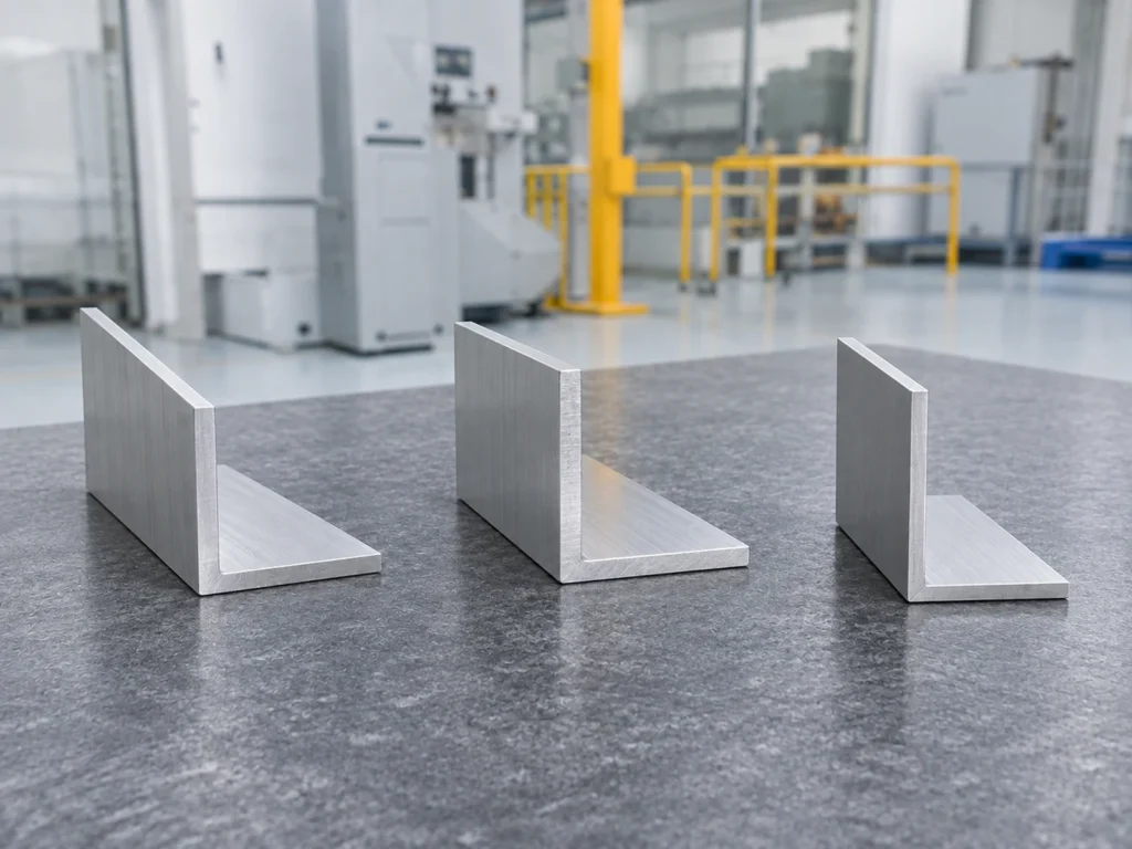
For a simple angle, identify both legs and the corner where they meet. Equal legs and unequal legs describe different section outlines. Keep the drawing visible when a quotation abbreviates the dimensions into a short size label.
In an aluminum tee vs angle review, show the mating parts beside the section. A tee’s flange may extend to both sides of its stem. An angle’s legs extend from their shared corner. Moving that branch changes the joint geometry even if the section fits inside the same outside rectangle.
SAF’s tee listing identifies width, leg, thickness and length, and defines its measurements as outside dimensions. Its table also names a rounded-corner variant. SAF’s equal-leg angle table lists A, B and T separately. Read the offered section’s drawing, including corner details, rather than treating a shape name as a complete specification.
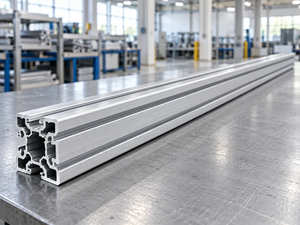
Do not confuse a plain tee with a T-slot framing extrusion. A slot, hollow chamber or joining system introduces additional geometry. A photograph showing the letter T somewhere within a complex profile does not identify a plain tee bar.
2. Compare aluminum tee vs angle with one defined example
Assume two ideal sections with square corners, constant 3 mm thickness and an outside envelope 40 mm across by 30 mm high. One is a tee with its stem centered beneath a horizontal flange. The other is an unequal angle with a horizontal 40 mm leg and a vertical 30 mm leg.
All values in this example are invented. The ideal model ignores corner radii and manufacturing variation. It makes a dimension-basis question easy to follow; it does not represent an available extrusion.
| Ideal section | Space within the stated envelope |
|---|---|
| Centered tee: 40 mm flange, 30 mm outside height | The stem below the flange projects 30 − 3 = 27 mm. Each flange overhang beyond the stem is (40 − 3) ÷ 2 = 18.5 mm. |
| Unequal angle: 40 mm by 30 mm outside legs | The inside horizontal span beyond the vertical leg is 40 − 3 = 37 mm. The inside vertical span above the horizontal leg is 30 − 3 = 27 mm. |
The tee’s 30 mm outside height is not a 30 mm clear stem projection below the flange. Those are different measurements. A request for an outside height of 30 mm and a request for a clear projection of 30 mm would describe different ideal sections.
These spans are geometric distances in the simplified model. They do not establish practical seating width, bolt clearance or usable tool access on a real part. A corner radius, surface condition or adjacent component can change the available space.
Equal area does not mean an equal joint
The ideal tee’s section area is 40 × 3 + 27 × 3 = 201 mm². The angle’s area is 40 × 3 + 30 × 3 − 3 × 3 = 201 mm². Subtracting the overlap in the angle prevents counting its shared corner twice.
The arithmetic gives equal section area, but it does not move the material into the same places. One shape has two flange overhangs and a central stem; the other has two legs meeting at an edge.
Do not turn the result into a claim of equal stiffness, strength or connection performance. Those require the actual geometry, material, loading and engineering evaluation. Area alone cannot approve a replacement.
A quotation that matches only the outside envelope and section area has therefore left an important part of the comparison unanswered. Ask it to identify the approved profile and show how the actual joint requirements are retained.
3. Review the proposed substitute at the joint
Separate a material offer from a design change. If the released part requires a tee, an angle proposal introduces a different section outline. Keep it clearly identified as a proposed alternative until the responsible team approves it.
For aluminum tee vs angle purchasing, compare the mating-face locations before asking whether the cut lengths can be shared. The relevant drawing should show which faces contact adjacent parts and which remain clear. Do not infer that relationship from a loose stock photograph.
Next compare the defined attachment features. A hole positioned on a tee flange may have a different relationship to the stem than a hole on an angle leg has to its corner. Retain the actual hole locations, clearances and edge requirements for engineering review.
Keep the offered alloy, condition and finish identified separately. A familiar shape label does not confirm them. Record any difference in the proposal so a geometry discussion does not hide a material change.
Only then connect the approved section to its cut blank. Show the required length and end geometry. Our angle-cutting drawing guide covers that production handoff; the comparison here addresses the earlier section-choice question.
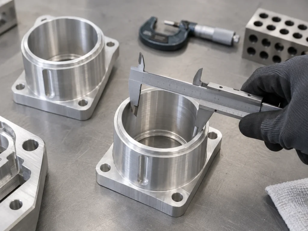
If later machining makes the finished attachment features, state that stage explicitly. Ask the quotation to distinguish supplied cut stock from finished components. The hole-position guide explains the references needed for the later operation.
Common questions about aluminum tee vs angle
Is a tee stem height always an outside height?
No universal interpretation should be assumed. Read the supplier’s dimension definition and the section drawing. Specify whether your requirement is overall height or the projection below the flange.
Can equal section area approve a replacement?
No. In the fictional example, both areas are 201 mm² while the attachment geometry remains different. Use the responsible engineering review for the actual joint.
Does a photograph prove the corner shape?
A photograph can help identify a candidate. Keep the controlled section drawing as the reference for corner details and the dimensions used in the purchasing request.
Request cutting for the approved section
Send JiurunCut the approved profile drawing and cut list. If the aluminum tee vs angle decision remains open, identify both proposed outlines and their approval status so the quotation does not silently choose a substitute.