
The stock is still on the feeder, yet a saw pauses as if it has disappeared. Later, a similar profile passes the same detection point without a warning. This is a diagnostic scenario, not a reported Jiurun customer incident. For a buyer specifying an aluminum saw photoelectric sensor, the useful question is how the proposed machine distinguishes a dirty optical path from a genuine change in stock position—and what the operator can safely check before restarting production.
A photoelectric sensor can be part of a stock-presence, position or counting function. Its exact job depends on the machine design. A sensor shown in a catalog, or a controller message in a demonstration, does not establish the sensing arrangement supplied with a particular quotation. Ask the machine builder to identify the physical detection point, the target, the signal used by the controller and the consequence of losing that signal.
A clean target and a dirty lens can produce the same question
Before changing a program, separate the possible causes of an unexpected sensor indication. Has the extrusion moved out of the intended path? Does its cross-section present a gap or reflective face at the detection point? Is the emitter or receiver misaligned? Have chips, fine residue or fluid mist reached the optical surface? Is a cable or connector intermittent? These are different faults, even if an operator sees only a missing-stock alarm.
Omron’s photoelectric sensor precautions explicitly include foreign matter on the emitter or receiver lens, optical-axis adjustment, target speed, wiring and strong light in a maintenance check. The source is general sensor guidance; it does not identify the components fitted to a Jiurun saw. The practical purchasing point is to request a diagnostic path that can separate target, optics, alignment and electrical input instead of treating every interruption as a software problem.
Record the symptom before cleaning or resetting anything: which profile was loaded, where it stopped, what the sensor indicator showed, what input the controller displayed and whether the fault appeared only after a production run. If the sensor was cleaned before those observations were captured, a recurring problem may be harder to reproduce. Never enter a guarded zone or reach toward moving stock to force a test; the supplier’s safe stop and isolation procedure governs inspection.

Check the aluminum saw photoelectric sensor input before blaming the cut
Ask the supplier to walk through one detection event with the actual quoted configuration. The witness should see the stock at the sensing point, the sensor’s own operation or stability indication where available, the controller input state and the machine action that follows. A lit indicator alone is not a completed test: it may report light received, an output state or a stability margin depending on the device. The meaning must come from that sensor’s manual and the machine’s electrical drawing.
Omron explains that some photoelectric sensors provide a stability indication or diagnostic output that can reveal reduced optical margin from dirt or misalignment before the ordinary output changes. That capability is sensor-specific. If the offered sensor has no such indication, the quotation should still explain a safe way to observe the controller input and confirm reliable detection under normal operation. Do not assume an alarm is available merely because a different sensor family supports one.
For a hollow or polished extrusion, repeat observation with the released profile in its approved orientation. The exact presentation of a slot, internal cavity or bright surface can matter more than the material label “aluminum.” If the supplier changes sensor type, bracket position, threshold or controller timing to pass the trial, keep the revised setup with the acceptance record. A trial on a round bar does not qualify a hollow frame section with a different surface and cross-section.
Make cleaning access part of the machine decision
The useful sensor position is not simply the place where a clean sample is detected once. It must be reachable for inspection after the machine is safely stopped, and the mounting should preserve alignment when routine cleaning is done. Ask where chips and mist will travel during the actual cut, whether a protective window or air arrangement is proposed, and how the operator can see and clean the optical surface without removing a guarded component unnecessarily. Any purge or shield is a proposed configuration item to verify, not a standard feature to infer from a photograph.
For an aluminum saw photoelectric sensor, cleaning instructions must follow the fitted device’s manufacturer. Omron’s guidance for its plastic sensor lenses warns against alcohol and organic solvents and advises gentle cleaning with a dry cloth or water. A SICK operating instruction calls for regular optical-surface cleaning and specifies a lint-free lens cloth for its device. These are examples of why one generic “wipe the sensor” instruction is inadequate; obtain the manual for the sensor actually supplied.
Ask who performs this check, where the instruction is posted and what condition triggers cleaning. A schedule copied from a clean showroom may not suit a cell running oily stock or a high chip load. The maintenance method should be compatible with the plant’s guarding and isolation rules. If cleaning requires repeated bracket removal, the buyer should treat that as an access and repeatability question before ordering the machine.
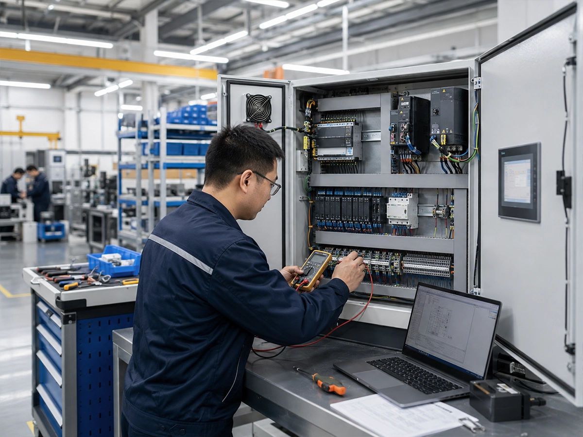
Define what the machine does with a weak or lost signal
The controller response should be written as a sequence, not as the vague promise “automatic detection.” At what point in the feed or cutting cycle is the input checked? Does a missing signal prevent the next feed, pause a pending cut or merely raise a message? What must the operator inspect before reset, and can a restart create an unintended part? These questions apply whether the detector is checking stock presence, a reference position or a counting event.
Do not confuse ordinary process sensing with a safety-rated protective function. A standard photoelectric sensor and a software alarm do not become a safety device because the saw stops in one demonstration. Safety functions require their own design, rating and validation. For the separate question of detecting the final usable length of a bar, see our bar-end sensor decision guide; this article concerns contamination, diagnostic margin and maintainable access rather than last-piece yield.
The Jiurun Machinery video below shows a JR-455CNC cutting machine and its feed and control area. It is useful equipment context for asking where a signal would be observed during a cycle. It does not show a photoelectric sensor cleaning procedure, a dirty-lens test, a particular quoted configuration, a customer’s stock or verified detection performance.
Record a clean run and a realistic working run
A clean bench demonstration answers only the first half of the buyer’s question. For acceptance, agree on the actual profile family, finish, orientation, stock presentation, cycle rate and normal chip or mist conditions. First observe the signal path on a clean setup. Then repeat after a representative production run under the supplier’s safe trial procedure. The comparison should show whether detection remains stable, whether residue has reached the optical path and whether the operator can restore the agreed condition without changing the machine setting blindly.
Record the profile drawing revision, fitted sensor make and model, mounting position, controller program or settings revision, relevant indicator states, fault message, stopped-machine inspection result and recovery action. If a controlled fault simulation is requested, let the supplier design and execute it under the applicable safety procedure. Do not spray fluid or place debris into a running saw just to manufacture a fault. The trial should also be repeated when a meaningful change to profile geometry, finish, bracket location or extraction route affects the optical path.
Collection and housekeeping are part of this context. A saw cell that carries chips toward the sensing point may need a different collection or shielding discussion from a cell where chips leave cleanly. Our fine-dust collection guide explains why visible coarse chips do not describe the entire waste route. That article does not approve a sensor installation or collector for your site; the equipment supplier and qualified site personnel must evaluate the actual arrangement.
Put the evidence in the quotation
A decision-ready quotation identifies the sensing purpose and location; the proposed sensor and any protective or diagnostic features; the controller’s response to a missing or unstable signal; safe inspection and cleaning access; and the profile-specific acceptance method. It should distinguish standard scope from options. If a supplier cannot yet specify the exact sensor model, ask for a functional description and mark the model and settings as items to close before acceptance, rather than silently treating an example component as the delivered one.
Send your profile drawing, finish and orientation, stock and cut lengths, expected chip or mist conditions, current symptom if there is one, and the desired machine response. Ask JiurunCut to review the cutting application and identify which detection and maintenance questions need a configuration-specific answer. The goal is a saw that can be assessed in the real cell, with an observable signal and a recoverable fault path—not a promise inferred from a clean catalog image.