
Side guides at a saw infeed seem simple until a new extrusion, a different surface finish, or a longer stock length reaches the machine. For a buyer, the useful question is not merely whether an aluminum saw has side guides. It is which face establishes the lateral reference, where that reference begins and ends, how the opposite side is adjusted, and whether the stock can enter the saw without being forced sideways. An RFQ that defines those conditions gives a supplier something testable.
This guide explains how to specify aluminum saw infeed side guides for a particular profile family and how to inspect the proposed arrangement during a changeover. It is a procurement and acceptance framework, not a statement that any pictured machine has a particular guide configuration or achieves a specified cut tolerance.
Define the job of the guide before choosing its hardware
An infeed has several separate jobs. Rollers or a support bed carry the stock. A feed mechanism advances it. A lateral guide limits its side-to-side path. The saw’s workholding and cutting process address the stock at the cutting zone. A side guide cannot make bent or twisted material straight, correct a height mismatch between conveyors, or establish the finished length by itself. Keep those functions separate in the purchase specification.
Start with a drawing of each representative extrusion or tube, including the face that may safely touch a guide. Mark the intended entry orientation, the stock length range, and any surface that must remain free of rubbing. If the part has ribs, open slots, a delicate finish, or a nonuniform width, an apparently convenient edge may be a poor datum. The supplier should identify the usable contact face from those real parts, rather than infer it from a nominal width alone.
Aluminum saw infeed side guides: choose the lateral datum and clearance
The first decision is which side of the material is the reference side through the infeed and into the saw entrance. Show that side on the drawing and ask the supplier to trace the contact path from the first guide element to the machine. A second, adjustable side may constrain wandering, but it must leave suitable clearance for the actual stock variation. A pair of guides pressed tightly against every section can turn a guidance problem into friction, marking, or a jam.
Ask how the reference side remains aligned when the guide is moved for a different profile. Does adjustment move only the opposite side, or can both sides shift? Are settings indicated by a scale, stops, a documented position, or a repeatable setup procedure? These are questions to verify against the proposed equipment; they are not features to assume. Record the guide setting together with the profile revision so the operator can reproduce the setup during a later run.
Use the material’s actual maximum and minimum width, including its manufacturing variation, when discussing clearance. Agree on the acceptable contact and surface condition with the supplier. Do not substitute the feed drive’s stated positioning precision for a finished-part tolerance: the latter also depends on material, clamping, blade, measurement method, and the agreed inspection plan.
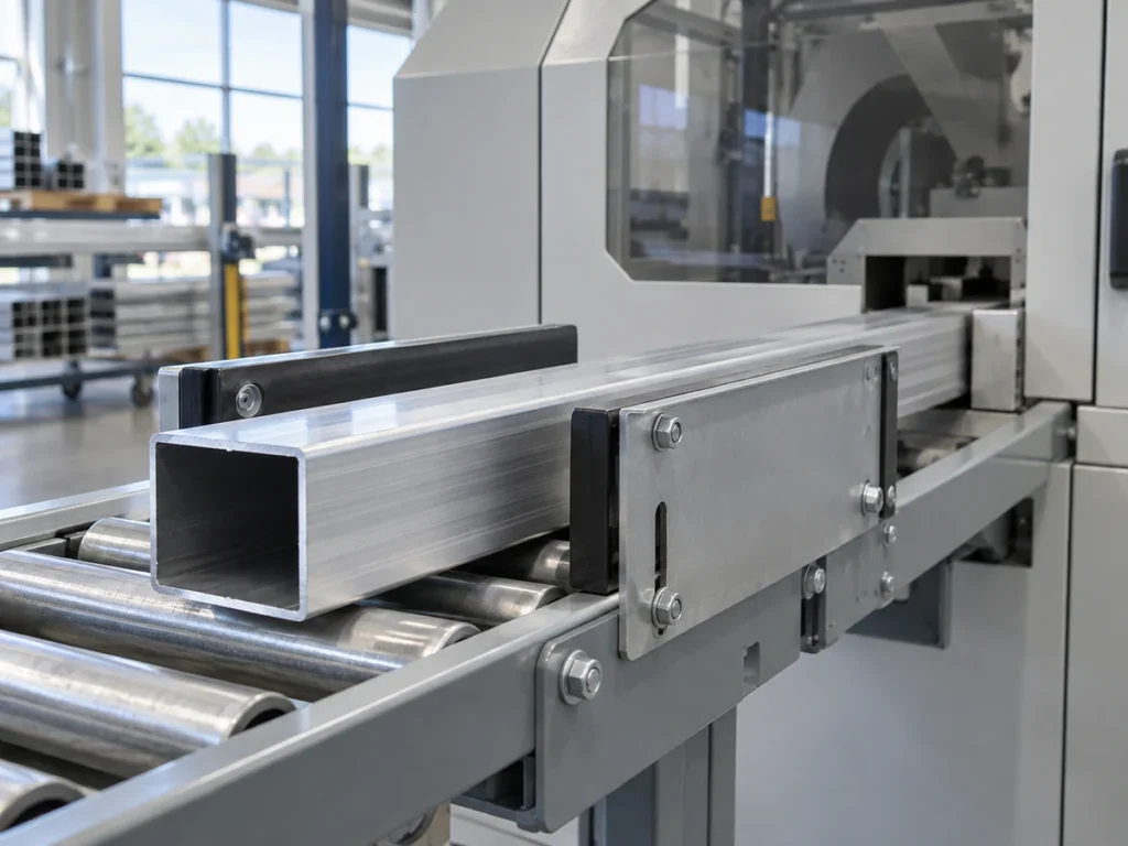
Trace the entire path into the saw
A guide can look satisfactory in one photograph while the critical transition lies outside the frame. Map the upstream table or conveyor, the roller top plane, each side-guide segment, any gap between frames, and the final entrance to the saw. Identify where the leading end first contacts a guide and where the trailing end loses support. Check whether a long profile can yaw as its center of mass passes a support gap.
Reference drawings should distinguish the vertical support datum from the lateral guide datum. If an existing roller table will be reused, supply its dimensions and photos, including height-adjustment points and the last rollers nearest the saw. Ask the supplier to show how the new and existing sections align. As a general conveyor-design reference, Interroll’s alignment-conveyor manual treats roller-top position and side-frame alignment as explicit setup items. That document describes Interroll equipment; it does not establish a Jiurun configuration.
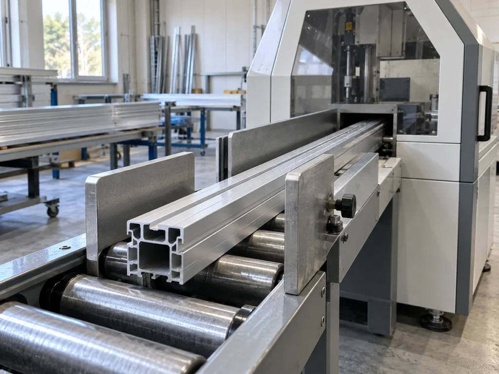
For a broader stock-envelope check before specifying the guides, see our aluminum saw feedability guide. The present decision is narrower: once a profile can be supported and moved, how will its lateral path be defined and checked?
Make adjustment practical for the real changeover
Ask the supplier to demonstrate the adjustment with at least two dissimilar profiles from the intended production mix. The useful evidence is a sequence: stop and secure the machine according to its procedure, remove or reposition the prior stock, set the guide, check clearance along the path, introduce the new section, and record the final setting. A single photograph of an adjustment knob does not show whether access, reach, or repeatability is adequate.
Different sections may call for different contact height as well as width. A thin-wall tube, a broad extrusion, and an asymmetric section need not present the same stable guide face. As a general design example, mk describes adjustable side rails with width and height options; this is a useful reminder to specify the adjustment axes, not evidence that a proposed Jiurun saw includes those options. Ask for a configuration drawing and a witnessed demonstration of the actual offer.
Define who is expected to perform the changeover, what tools are required, which positions must be recorded, and how the setting is checked before production resumes. An agreed procedure matters more than an unsupported promise of a particular changeover time. If a guide must be removed for one profile family, request a safe storage and refitting method and inspect the resulting stock path.
Put these questions in the RFQ
- Stock definition: Which drawing revisions, section sizes, lengths, straightness conditions, and surface finishes will be represented in the trial?
- Datum: Which face may contact the fixed reference, and where does that reference continue into the saw?
- Adjustment: What width and contact-height changes are needed, who makes them, and how is each setting recorded?
- Interface: What are the roller-top, frame, gap, and entrance dimensions of any existing infeed equipment?
- Surface condition: What rubbing, marking, or debris accumulation is unacceptable on each profile?
- Acceptance: Which samples will be run, what observations will be logged, and who approves a changeover?
Attach a marked layout rather than relying on phrases such as “suitable for all aluminum profiles.” If a requirement is undecided, mark it for joint review. A supplier can then state what is included, what must be measured on site, and what requires a trial or a revised design.
Witness the guide path with representative stock
Begin with a stopped setup inspection under the machine’s documented safety procedure. Confirm that adjustments are secured, that hands cannot be drawn into exposed nip or moving points during the planned operation, and that the operator has the necessary guarding and instructions. OSHA’s general machine-guarding rule is a safety reference, not a claim that a particular saw or installation has been certified to it. The responsible site team must assess the actual machine and local requirements.
Then run the agreed sample matrix under controlled conditions. Include the section most likely to tip or yaw, the longest practical stock, and any profile whose finish makes guide contact sensitive. Watch the leading end as it enters, the middle as support transfers between rollers, and the trailing end as it approaches the saw. Note where the material contacts a guide, whether it rubs or catches, whether chips accumulate, and whether the operator needs to push it sideways. If a trial fails, record the location and condition rather than merely reporting that the stock “does not feed.”
After each changeover, verify the setting against the marked drawing and run the agreed cut-and-inspection plan. Record finished-part measurements separately from guide-path observations. Our acceptance measurement guide explains why the measurement method and acceptance criteria should be agreed before results are interpreted. A smooth entry alone does not prove dimensional performance.
What the pictures and video can establish
Illustrative equipment views can help a buyer point to rollers, side contact surfaces, and adjustment locations when discussing an RFQ. They do not identify the final configuration for a quotation, prove that a particular alloy or profile was trial-cut, or demonstrate an accuracy or throughput figure. The same limit applies to a general machine video: use it to understand an equipment or handling sequence, then request drawings and a representative trial for the proposed purchase.
General Jiurun equipment footage from the @jiurunmachinery channel. It illustrates a saw and feed sequence only; it does not show or verify the material, side-guide setting, model configuration, customer, trial, cut accuracy, or performance discussed in this article.
Send a focused inquiry
Send Jiurun the profile drawings and revisions, a list of stock lengths and surface conditions, the intended entry orientation, photographs and dimensions of any existing infeed, and the sample matrix you want to witness. State which side should be the reference if you already know it; otherwise ask the engineering team to recommend a datum and explain the trade-off. Request a drawing of the proposed guide path, an adjustment method for each profile family, and a written acceptance plan. Contact Jiurun with that package so the configuration can be evaluated against the real stock and installation.