
Aluminum saw acceptance measurements need a shared method. Two teams can measure the same cut aluminum part and reach different pass/fail conclusions without either team being careless. One checks a loose extrusion on a bench; the other pulls it into an assembly fixture. One includes a raised burr in the length reading; the other removes the burr before measuring. A digital display may show many decimal places, yet its resolution alone does not establish the uncertainty of the result.
When buying an aluminum cutting saw, agree how the finished part will be measured before treating a tolerance as an acceptance promise. The drawing defines the required part; the inspection agreement defines how the buyer and supplier will decide whether a measured part meets it. This guide gives purchasing, engineering, and quality teams a practical way to write that agreement into the RFQ and acceptance plan.
Why aluminum saw acceptance measurements belong in the RFQ
A quotation that says “cut length within tolerance” leaves important questions open: which surfaces establish the length, whether the part is free or restrained, how an angled end is contacted, which samples are checked, and what happens when a reading falls near a limit. Those omissions can turn a satisfactory equipment demonstration into a disputed part inspection.
Start with the released drawing and its revision. List the characteristics that matter to assembly, such as overall cut length, end angle, squareness, burr condition, or a feature-to-end distance. State the relevant datum or reference face for each characteristic. Do not assume the saw feed specification is the finished-part tolerance. Feed positioning, clamping, blade condition, extrusion geometry, temperature, and the inspection setup can all affect the result observed on a cut part.
1. Define the part condition before anyone takes a reading
Identify the exact profile, alloy/temper if relevant to the application, cross-section, wall thickness, and cut orientation. Record whether inspection occurs immediately after cutting, after deburring, after a stabilization period, or after another process. If the part has protective film, say whether it stays on during measurement. A tolerance claim made for one condition should not silently become a claim for a different condition.
For long or thin extrusions, agree whether the part is measured in its free state on defined supports or in a specified assembly restraint. A bowed or twisted profile can change the apparent distance between contact points when someone presses it against a straightedge. If a fixture represents the installed condition, define its locating faces and clamping force or procedure. If free-state geometry is the requirement, do not use assembly restraint to hide an out-of-condition part. Treat this as a drawing and application decision, not a generic saw setting. For the distinct question of restraint, see our free-state versus assembly-restraint inspection guide.
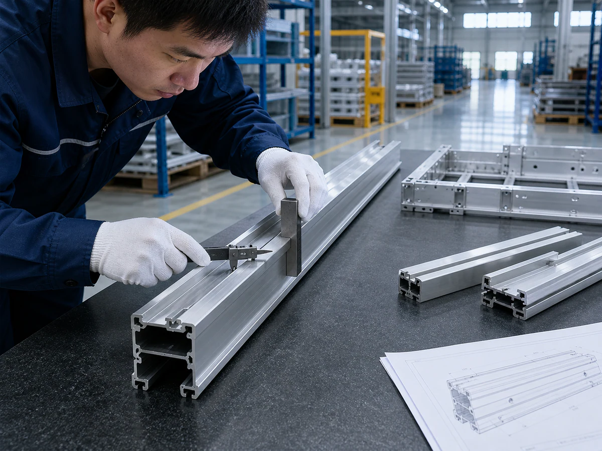
2. Specify contact points for length and angle
“Measure the length” is not enough for a profile with a mitered end, radius, lip, hollow section, or localized burr. Name the two faces or points that establish finished length, the support orientation, and the instrument or fixture used. A drawing may call for a projected length along a reference axis rather than the shortest edge-to-edge distance. For a miter, identify the datum edge and the angle convention so that a 45-degree reading is interpreted on the same side of the cut by both teams.
Decide how to treat saw marks, chips, and burrs. A burr can interfere with a caliper jaw or a stop face; removing it may change the measured condition. The acceptance plan should state the allowed cleaning or deburring step and whether burr height is evaluated separately. Keep a photo or simple sketch of the contact setup for the first approved part. That record is much more useful in a disagreement than a number without context.
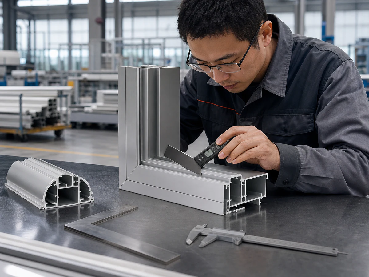
3. Match the instrument and fixture to the decision
Select a measurement method that can contact the intended feature repeatably. A hand caliper may be useful for an accessible dimension but awkward for a long extrusion, a recessed feature, or an angled face. A length stop, gauge block, height gauge, angle gauge, coordinate measurement, or dedicated fixture may be more appropriate depending on the drawing. Record the instrument identity, its calibration status, and the measurement setup used for acceptance.
Calibration is necessary for confidence in an instrument, but a calibration sticker does not by itself prove that a particular part result is traceable or that the method is suitable. The US National Institute of Standards and Technology explains that metrological traceability belongs to a measurement result supported by a documented chain and uncertainty. For purchasing, the practical question is whether the selected tool, fixture, operator method, and environment can make the required pass/fail decision reliably.
Check repeatability with representative profiles, not just an easily measured block. If two trained inspectors obtain materially different readings on the same retained part, settle the method before accepting or rejecting a machine. Consider temperature, support spacing, contact force, zero setting, and wear in a fixture as possible contributors. This does not require inventing an uncertainty number in a sales quotation; it requires agreeing how the measurement system will be qualified for the stated tolerance.
4. Agree what happens at the tolerance boundary
A measured value close to a drawing limit is a decision problem. The buyer and supplier should agree whether an observed reading is compared directly with the limit or whether a stated guard band or other decision rule applies. The method must identify who bears the risk of an incorrect acceptance or rejection and what evidence will be reviewed. The BIPM/JCGM guide on conformity assessment addresses how measurement uncertainty enters this kind of decision. NIST also notes that choosing a decision rule involves risk and cost choices.
Do not add a guard band or a stricter tolerance after the purchase and call it the original saw specification. Conversely, do not claim a marginal reading passes merely because the display rounds favorably. Put the rule, rounding convention, and escalation path into the RFQ or acceptance document. When a part is disputed, retain it and repeat the measurement under the agreed method before changing offsets, replacing a blade, or assigning fault.

5. Separate machine acceptance from part acceptance
A factory acceptance demonstration can show that the selected configuration runs the specified profile and produces inspectable samples under documented settings. Site acceptance must also consider installation, power and air supply where applicable, operator training, handling, and the actual incoming material. Neither event automatically proves that every future production part will meet a drawing tolerance. Our factory-versus-site acceptance guide separates the two test settings in more detail.
For a meaningful demonstration, identify the sample profile and drawing revision, blade and clamping arrangement, cut orientation, inspection method, and how many parts will be examined. Record raw measurements, not only a “pass” label. First-part checks and ongoing sampling serve different purposes; write both into the production plan if needed. Treat process capability, cycle time, and scrap rate as separate questions requiring their own representative trials and evidence.
RFQ checklist: make the acceptance question answerable
- Drawing and material: Send the released drawing revision, profile section, material specification, part length range, and expected cut orientation.
- Characteristics: Mark the exact dimensions and cut-face conditions that determine assembly fit; distinguish required limits from preferences.
- Datum and condition: State reference faces, supports, free-state or restrained measurement, deburring condition, and any protective-film requirement.
- Measurement system: Name the gauge or fixture, contact points, instrument identification, calibration evidence, and repeatability check.
- Decision rule: Agree rounding, treatment of measurement uncertainty near the limit, retained-sample procedure, and who resolves a disagreement.
- Acceptance plan: Specify representative sample quantities, factory and site checks, raw-data records, and any separate throughput or waste trial.
If the drawing is incomplete, ask the design owner to resolve datum and tolerance questions before soliciting a guaranteed result. A saw supplier can discuss a suitable cutting and clamping configuration, but it cannot responsibly infer every assembly-critical feature from a single nominal length.
What to ask Jiurun before specifying a saw
Share the actual extrusion drawing, target output range, cut orientations, available sample material, and the proposed inspection plan. Ask Jiurun to identify which machine configuration and demonstration conditions should be evaluated for that application. Request that any sample-cut conclusion be tied to the tested material, setup, measurement method, and recorded observations. If the acceptance method changes later, revisit the conclusion instead of treating a previous result as universal.
Next step: Contact Jiurun with your drawing and acceptance checklist to discuss a representative saw evaluation. The images on this page illustrate inspection concepts; they are not evidence of a particular configuration, customer, trial, or guaranteed performance.