
A bright dent appears on a thin-wall extrusion before the blade reaches it. The pressure gauge looks normal, so reducing the regulator setting may seem like an easy answer. Yet an aluminum saw clamp closing speed question is about the jaw’s approach and contact, while the pressure question is about the holding condition after contact. A buyer needs to observe both before accepting a machine or changing a setting.
This guide is for a saw with a powered clamp and a representative aluminum profile. It does not assign a speed, force, air pressure or valve type to a particular Jiurun model. The installed pneumatic diagram, machine manual and supplier-approved commissioning procedure decide what can be adjusted on the delivered machine.
The dent begins before the cut
Separate the sequence into jaw approach, first contact, full seating, cut, and release. A mark made at first contact has a different investigation path from stock that slips only after the blade enters. Record which phase produced the change. Do not infer a speed problem merely from a damaged part: a hard jaw edge, trapped chip, unsupported hollow wall or wrong locating face can create the same visible mark even at an acceptable closing rate.
The featured clamp-contact image is a related illustration of pad placement on hollow stock; it is not a measured closing-speed trial or evidence that this profile was dented.
For a hollow section, mark the top, bottom and datum faces on a sacrificial test piece approved for the trial. Note the distance from the end, the profile orientation and the support under the jaw. Examine the mark before cutting and again after the first cut. This simple timing distinction keeps a clamping contact question from becoming an unsupported blade diagnosis.
Aluminum saw clamp closing speed: follow three events
First, watch when the closing command occurs relative to stock arrival. Second, observe the motion from first movement to contact and whether the profile shifts or the jaw visibly bounces. Third, confirm that the stock remains located when the cutting cycle begins. A video taken from the approved viewing position can help the supplier compare these events; no one should reach through a guard or defeat an interlock to obtain a better angle.
Keep the sample and the video together. Record the profile drawing and wall thickness, jaw contact location, stock support, program or cycle identifier, air-supply reading in the relevant phase, and the first-off cut result. A single snapshot of a stationary gauge cannot show the jaw’s travel or the contact transient. Nor can a controller’s “clamp closed” signal alone prove that a thin wall was not struck or deformed.

Speed, holding and control are separate questions
A pneumatic speed controller changes flow in a particular circuit. It is not a substitute for identifying the permitted holding condition or for checking the jaw contact geometry. SMC’s cylinder manual distinguishes meter-in from meter-out control and describes gradual speed adjustment for its cylinder. Festo’s flow-control explanation likewise connects one-way flow control with cylinder motion. These are component principles, not a recommendation to fit a particular valve or copy a setting onto a Jiurun saw.
Ask the supplier to identify the actual clamp actuator, valve, speed-control device and adjustment authority in the supplied machine. A regulator, a flow-control needle, a controller dwell timer and a jaw stop do different jobs. Changing one because the other is poorly understood can leave a machine that closes more slowly yet still contacts the wrong face, or one that moves quickly but fails to hold the stock during the cut.
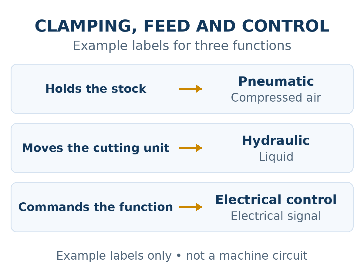
What to check when the jaw seems too fast
Use the observed pattern to choose the next check, instead of turning a knob by guesswork:
- Impact at first contact: preserve the sample and ask the supplier to review approach motion, cushioning or the installed flow-control method, as applicable.
- Local dent with no obvious snap: inspect the contact pad shape, alignment, trapped chips and support beneath the hollow wall.
- Mark appears only during cutting: compare stock location before and after blade entry; investigate holding and cut load as a separate question.
- Scuff appears on the next feed: confirm actual jaw clearance after the release command. The clamp-release feedback guide addresses that later phase.
If a gauge falls while the blade is engaged, the clamp pressure-sag trial covers the dynamic holding question. These branches can coexist, but evidence from one does not establish the cause of the other.
Release the setting through a witnessed trial
Agree on one approved profile and orientation, the jaw contact face, acceptable surface condition and the first-off cut criteria. The machine supplier or authorized technician should make any permitted adjustment using the machine-specific procedure. Compare the same stock and setup before and after the change, record the final setting or documented control reference, and retain both sample results. A smooth-looking close alone is insufficient if the profile shifts during cutting or the cycle cannot repeat safely.
For service work, isolate the machine’s relevant energy sources and control stored pneumatic energy under the site’s procedure before accessing the clamp circuit. OSHA’s hazardous-energy guidance explains why stored pneumatic energy matters during machine maintenance; local requirements and the actual saw instructions still govern the work.
The following Jiurun Machinery video shows an automatic aluminum saw’s feed and cutting area. It is useful for discussing where a buyer would observe stock arrival before clamp engagement. It does not measure jaw closing speed, document a valve setting, or prove that the test profile in this article was cut on the filmed machine.
Put the contact condition in the machine inquiry
Send Jiurun the profile drawing, wall thickness and finish requirement, photographs of the mark, the intended loading orientation, the planned cut range and any cycle video made from the approved viewing position. Ask which quoted clamp arrangement contacts the profile, what machine-specific adjustment and isolation instructions will be supplied, and how a witnessed first-off trial will judge both surface condition and part location. This makes aluminum saw clamp closing speed an observable acceptance question without promising that one universal speed or pressure suits every extrusion.
Contact JiurunCut with those details to discuss a representative machine trial and the evidence needed for your production decision.