
Aluminum saw clamp pressure sag is a buying and acceptance-test question: will the available air pressure at the clamp circuit remain adequate during the part of the cycle when the stock must stay located? A regulator gauge read while the saw is idle is only a starting point. It cannot, by itself, show what happens when several air consumers operate together.
This guide gives buyers a practical way to ask for a cycle record, compare it with cut-part results, and define what belongs in a quotation. It does not prescribe a universal pressure setting. The machine supplier and a qualified pneumatic technician should define the permitted measurement point, required pressure range, guarding, and safe test method for the actual configuration.
Why aluminum saw clamp pressure sag hides behind an idle reading
In an aluminum saw clamp pressure sag investigation, a supply regulator can show a normal value between cycles while a restriction, long run, undersized line, shared demand, or upstream supply variation causes a temporary drop at a downstream point when air flows. The size and timing of any drop depend on the actual circuit and demand. A buyer should therefore ask for pressure versus time at a specified point, together with a log of clamp and cut events, instead of accepting a single idle reading.
For general compressed-air context, the U.S. Department of Energy sourcebook explains pressure drop and time-based logging, and SMC’s cylinder troubleshooting guidance identifies supply and flow-path conditions among possible causes of insufficient operating pressure. These sources explain general principles; they do not specify a Jiurun saw’s circuit or prove any particular machine performance.
Define the part and the phase that matters
Start with the extrusion that is hardest to hold without distortion: its section drawing, wall and rib pattern, stock length, surface requirements, target cut length, and allowed finished-part variation. Identify where the profile is supported and where contact is permitted. A rigid rectangular tube, a multi-cavity section, and a thin open profile may need different contact or support decisions even if the same supply gauge reading appears acceptable.
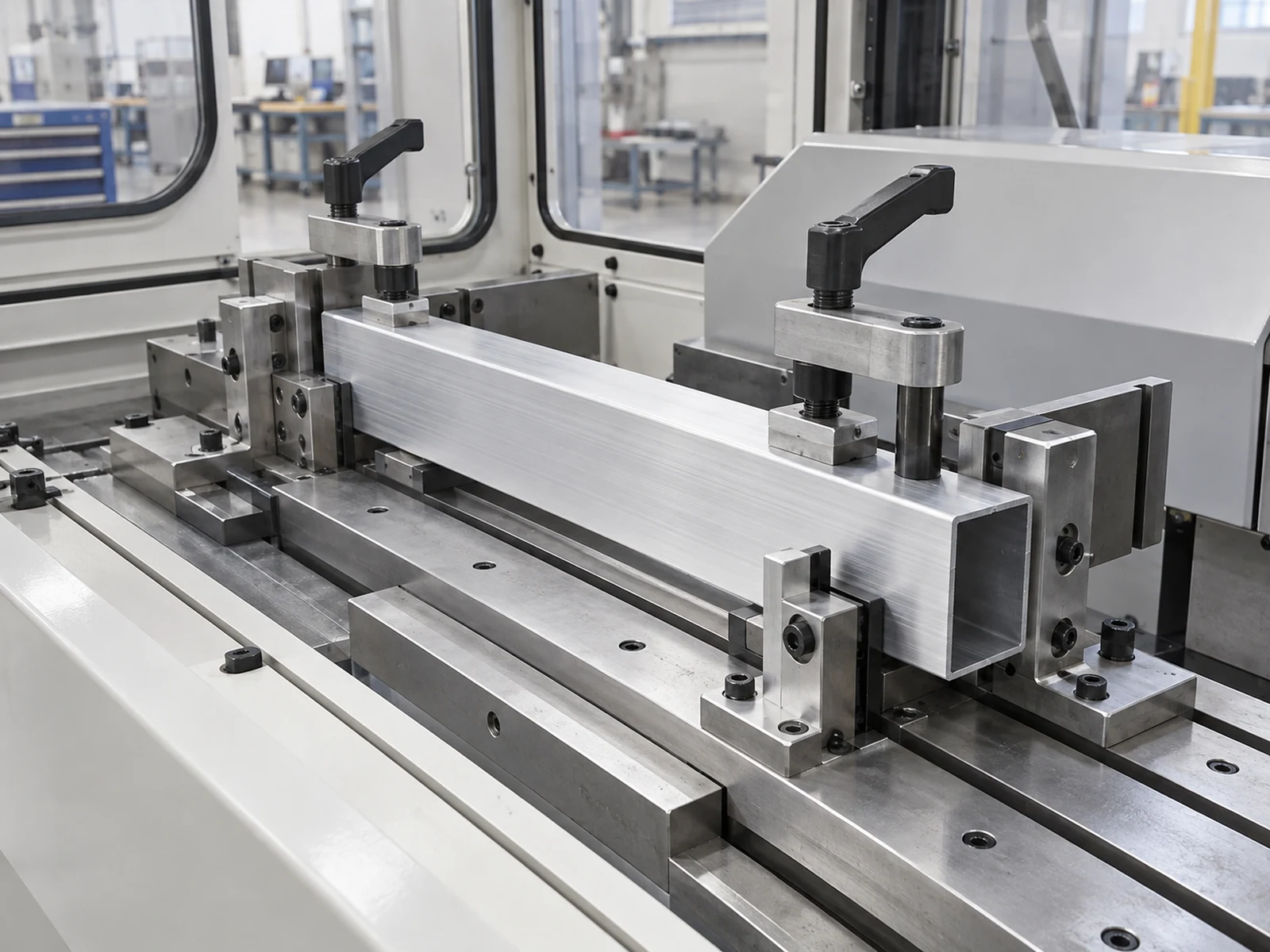
Next, label the sequence: stock positioning, clamp approach, full contact, blade entry, cutting, blade return, release, and feed. The relevant question is whether the hold state remains correct while cutting force can disturb the workpiece. Pressure at an unrelated point or recorded after the critical moment may miss the issue. Ask the supplier to name the sensor location and explain how it relates to the holding actuator; a source gauge and a local point-of-use sensor answer different questions.
Request a repeatable dynamic trial
An aluminum saw clamp pressure sag acceptance trial records more than a minimum number on a display. Agree these fields before the demonstration:
- Test article: profile drawing, alloy/temper if relevant, sample length, surface condition, and quantity.
- Machine state: approved clamp arrangement, contact pads, support positions, feed mode, blade, and programmed sequence.
- Air context: facility supply range, agreed test connection, other consumers that will be active, and whether the test uses the buyer’s plant air or a supplier source.
- Trace: timestamped pressure at each agreed point, with clamp, blade, feed, and release events aligned on one timeline.
- Parts: identification of first, middle, and last cuts in a run, with the buyer’s chosen measurement method and rejection criteria.
- Intervention: any stop, reset, adjustment, or rejected part recorded rather than removed from the result.
A qualified person should use the machine maker’s approved ports and procedure. Do not loosen a live fitting or defeat guards to obtain a reading. If the agreed sensor position is unavailable, record that limitation and ask the supplier what evidence can be provided safely. The DOE sourcebook describes pressure and demand logging as a diagnostic method for intermittent loads; it is a reason to examine the operating cycle rather than an idle number alone.

Read the trace alongside the finished parts
A brief dip is not automatically a failed cut, and a flat trace is not automatically an accepted part. The agreed pressure range must come from the actual actuator and holding design. Compare the pressure trace with contact, blade entry, and any movement or part-quality event. Record whether a low value occurred before full contact, only during another device’s demand, or throughout a sustained run. Ask the supplier to explain how the clamp-state logic responds when the agreed minimum is not met.
Then inspect cut length, end squareness, burr condition, visible witness marks, and any critical assembly feature using the buyer’s drawing and inspection method. A pressure reading is an input to diagnosis; it cannot replace a measured sample. If the parts pass only after a quiet single cycle, repeat with the normal production sequence and expected simultaneous air demand. If the parts fail, retain the trace and the identified pieces so the supplier can distinguish air availability from contact geometry, support, blade condition, or another cause.
For the mechanical side of this decision, the separate manual versus pneumatic clamping trial plan addresses clamp method and profile contact. The air-storage demand guide addresses short peaks versus sustained facility demand. This article is specifically about observing the pressure available during the clamp-and-cut sequence and pairing that record with accepted parts.
Put the acceptance condition in the RFQ
Ask for a written response to five questions. Where will the pressure be measured? Which cycle events will be time-aligned to the trace? What supply range and concurrent consumers are assumed? What stock and sample count will be tested? What part and machine-state evidence will determine acceptance? Require the quotation to separate standard supplied components from optional sensors, data logging, plant-air preparation, and site commissioning. Do not infer that a quoted saw includes pressure logging or a particular air preparation package unless the supplier confirms it.
A concise acceptance statement might read: “During a trial on the supplied profile drawing, record the approved point-of-use pressure trace through the agreed production cycle and identify the corresponding cut pieces. Evaluate both the trace against the supplier’s documented operating requirement and the parts against our drawing.” The numeric threshold, duration, sample size, and allowable variation must be filled in for the specific application rather than copied from a generic article.
A related equipment video
The Jiurun video below shows a general aluminum-saw equipment view. It is useful for seeing machine context only; it does not demonstrate clamp pressure, the profile in this guide, a quoted model configuration, a customer trial, or a performance result.
Send a better request to the supplier
Include the extrusion drawing, cut length and tolerance, surface and burr limits, expected cuts per shift, facility-air information, and the parts that must be accepted. Ask Jiurun to confirm an appropriate saw and clamp arrangement, the safe pressure-observation method, and a sample-cut acceptance plan for your material. Send the application details to Jiurun so the discussion starts with a documented test rather than an idle gauge photograph.