
Aluminum profile orientation at the saw is a purchasing question whenever a section can be loaded more than one way but the finished member cannot be reversed. A rectangular outside envelope, a cut length and an angle alone may leave the open face, rib, visible face or handed end undefined. The result can be a quotation that appears to cover the job while the proposed support, clamp or production sequence has never been checked against the released part.
This guide shows how to give a saw supplier one unambiguous orientation package, how to compare the quoted setup, and what to witness in a representative trial.
Aluminum profile orientation starts with the released member
Before asking whether a saw can rotate its blade, establish what your factory must deliver. List each stock section by its actual drawing and revision, the finish and protected faces, the finished length and end geometry, any left- and right-hand variants, and what subsequent assembly or machining uses as its reference. If you buy cut-to-length blanks for later work, state where the saw’s responsibility ends. If you buy finished frame members, include the mating end and connector checks that make the member acceptable. These are different purchase scopes even when the starting extrusion is the same.
A symmetric section with square ends may be reversible. An asymmetric channel, unequal angle, slot or ribbed hollow section may not be. Even a symmetric extrusion can become handed after a different end alteration or an angled cut. MISUMI’s extrusion ordering guide explicitly distinguishes left and right ends and notes that non-symmetric sections or unlike end alterations are not reversible under its own ordering convention. That is a useful example of why a supplier needs your stated convention; it is not a universal orientation rule for every extrusion. See the MISUMI extrusion position and alteration guide.
Give the supplier three separate views
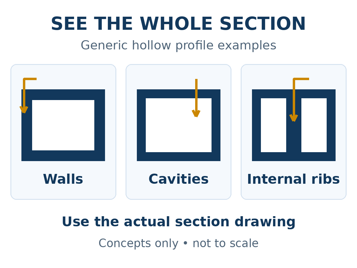
First, provide a cross-section view with a named viewing direction, such as “look from the incoming-stock end toward the saw.” Mark one unmistakable feature as the orientation key: open side, unequal leg, internal rib or finished face. Label the face or feature that must contact a reference during measurement.
Do not rely on “top” if the stock may be loaded upside down during a later operation. State the drawing revision and whether the view is first-angle or third-angle projection. Autodesk explains that a base view controls projected-view orientation and that the drafting standard controls projection layout; the Autodesk drawing-view reference is a useful reminder to label the actual view, rather than assume every reader interprets the sheet in the same way.
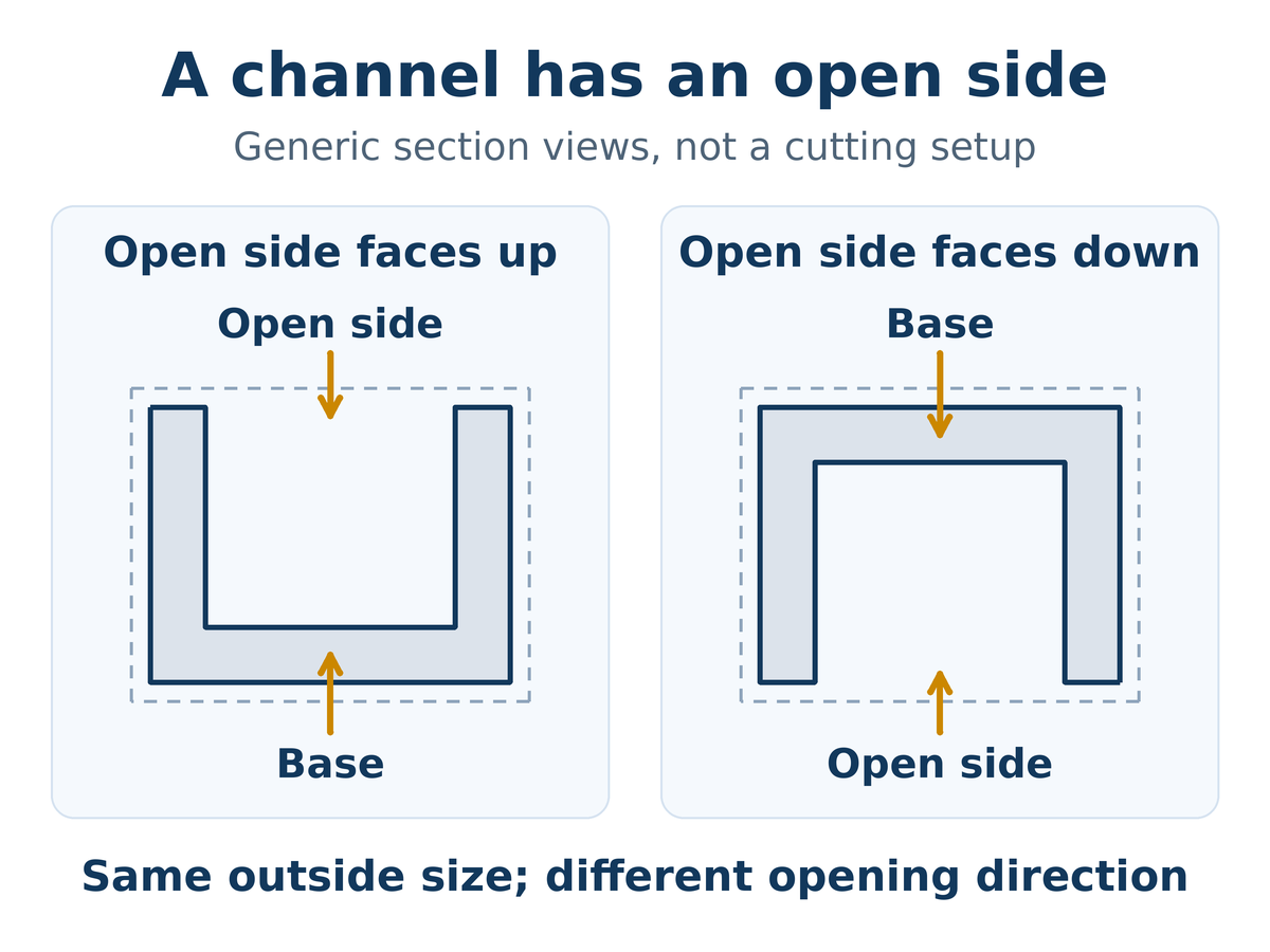
Second, add a longitudinal view that identifies the incoming-stock direction and the finished part’s two physical ends. Name those ends A and B, or use your own controlled drawing convention. If you write left and right, say whether they are seen while facing the saw, following stock travel, or viewing the completed member. A cut list should carry the same end names as the drawing. Never assume that flipping the stock, turning a part on the inspection bench, or reversing the saw’s feed direction preserves the handed result.
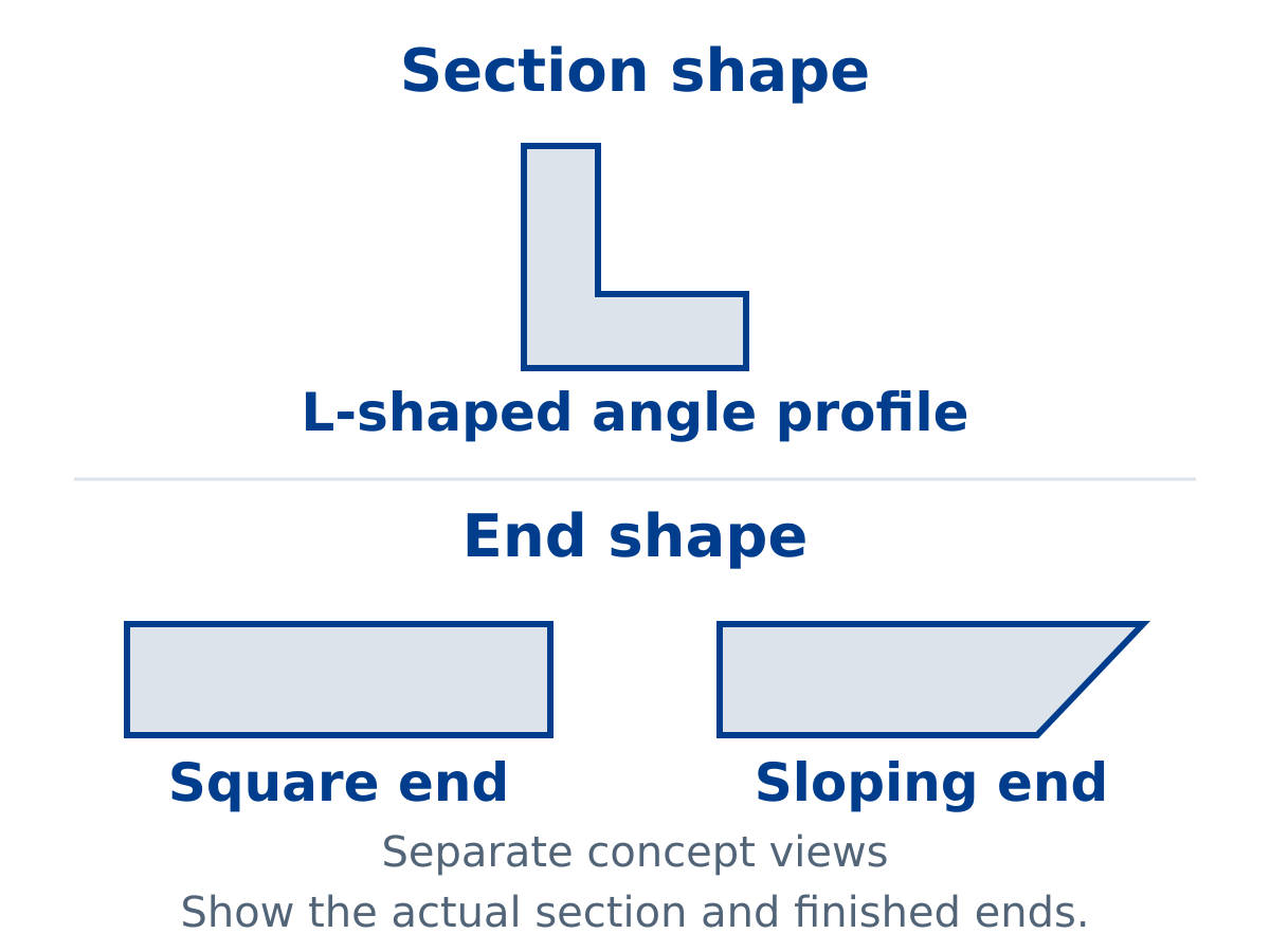
Third, give an end view or clear isometric detail where the section geometry and end angle meet. An end angle relative to the length does not by itself identify which wall is long, which finished face is exposed, or which part is the mirror mate. An L-shaped cross-section is also not the same thing as an angled end cut. The illustration below separates those questions, but the purchase decision needs the actual part drawing.
Convert the views into a usable RFQ schedule
Attach a short part-family schedule beside the drawings. For each member family, record: stock profile and revision; incoming length form; the marked section feature and its viewing direction; reference face or datum; End A and End B treatment; whether a mirror mate exists; required output form; and the inspection method that decides acceptance. Add batch size and changeover frequency only from your own production plan. Keep tolerance and finish requirements on the approved drawing, or quote them explicitly if there is no released drawing. Do not let a supplier fill missing values by inference from an unrelated photograph.
For example, a hypothetical open channel might be listed with its opening facing the operator in the specified cross-section view, a protected outer face, square End A and a handed miter at End B. A different, hypothetical ribbed section might require the internal rib to be supported during clamping but have square ends. These examples are decision patterns, not claims about a Jiurun model, a customer component, achieved accuracy or suitable clamp pressure. The supplier must check the actual sections and fixtures.
Ask what the proposed machine does with that orientation
The quote should describe the physical route from incoming stock to accepted member. Ask where the operator or loader sees the orientation key, what references the section on the infeed, how the profile is supported at the cut, whether a family change needs different contacts or guides, and what prevents an incorrectly oriented batch from silently continuing. The answer may be a controlled manual check, a fixture or an offered sensing arrangement; request the exact offered configuration and evidence rather than assuming an automatic feature exists.
Pay attention to the interface between the side guide, clamp and blade. A guide may establish a lateral datum without holding a thin wall, while a clamp may contact an outer face without controlling rotational clocking. The supplier should show both contact locations on the actual profile, identify faces that must remain unmarked, and explain how a changeover is reset and approved. Our separate infeed side-guide buyer checklist addresses the guide itself; the orientation package here decides whether that guide is referencing the correct face for each member.
For mitered families, ask how End A and End B are produced and kept identifiable. One proposed route may cut one end, rotate or reorient the work, then cut the other; another may use a different head or fixture arrangement. Neither route is automatically superior.
Compare them against the same delivered member, including visible-face protection, maximum stock shape, shortest acceptable piece, changeover work, scrap disposition and the evidence needed after a setup change. If the supplier proposes cutting two mirror pieces from one stock segment, verify the actual section, kerf allowance, mating hand and release checks rather than assuming a shared cut makes two acceptable parts.
Design a trial that can fail for the right reason
Use samples from the actual profile family where possible, with the correct finish and a clearly controlled drawing. Include at least one easy reference part and the orientation-sensitive variants that drive the buying decision. Observe a cold setup or agreed changeover, the first-piece identification, the placement of the profile in its guides and clamps, the two finished ends, and the way parts remain separated or labeled after cutting. The trial record should name the machine configuration, blade and fixture actually used, input stock, drawing revision, setting changes and operator actions. A video clip or a good-looking cut face cannot substitute for that record.
Measure from the released reference faces with an agreed method and make the pass/fail rule explicit before the trial. Check not only length and angle but also the hand, orientation key, protected surface and fit to the mating component when the purchase scope requires it. Keep rejected or uncertain pieces identified until the responsible person decides their disposition. See our acceptance-measurement guide for agreeing the measurement method; do not transfer a feeding-position specification into a guarantee of finished-part accuracy.
Compare quotations on the same deliverable
A low equipment price can hide added fixtures, operator marking, first-piece checks or downstream sorting. Build a comparison table with the same drawing set and accepted output for every vendor: which profile variants are covered; included supports, clamps and guards; who prepares and approves changeover recipes; handling of mirrored ends; sample and factory-test responsibility; training; documentation; and exclusions. Mark every capability as shown, supplier-confirmed but untested, optional, or outside scope. The buying decision is then about a complete route to an accepted member, not a headline number of axes or an unexplained machine photo.
Do not make a universal rule from the illustrated sections. A reversible symmetric member may need only a simple reference and cut list; a handed, coated or hollow section may need a more deliberate fixture and release method. The useful RFQ is the smallest complete packet that makes that distinction visible to every bidder.
General equipment video
The video below is from Jiurun Machinery’s YouTube channel and shows general saw/feed equipment footage. It is an equipment-flow example only. It does not document the profiles pictured above, the article’s hypothetical member families, a quoted model configuration, a customer, a trial cut or any performance result.
Send a quotation package that can be answered
For a useful review of aluminum profile orientation at the saw, send the profile drawings and revisions, labeled section and end views, a family-by-family cut schedule, actual sample stock or clear samples of the section, the target output form, the protected faces, the proposed batch mix, and the agreed acceptance checks. Ask the supplier to mark assumptions, exclusions and the evidence it can show for every orientation-sensitive variant. If your drawings are still provisional, say which geometry and hand are unresolved and request a conditional review rather than a false promise.
Contact JiurunCut with that packet to discuss which cutting arrangement merits an actual sample review. We can compare the stated job and ask for a demonstrated route; final suitability depends on the released stock, configuration and acceptance trial.