
Aluminum DIN rail orders need more than a length and the word “rail.” Identify the exact profile, material, perforation pattern and supplied condition before planning the cut. A mounting rail inside a control cabinet is a separate item from the cabinet frame, an ordinary channel or a complete electrical assembly.
This guide organizes five procurement checks: product identity, length reference, mounting holes, cut-end acceptance and delivered scope. Use the approved rail and assembly drawings to resolve each one. It is a purchasing and cutting handoff guide, not an electrical installation or protective-conductor design procedure.
Read the rail designation before the cut list
- Match the full part number and profile drawing.
- Keep total length and end-to-hole position separate.
- Assign mounting and electrical acceptance to the responsible assembly owner.
On this page

1. Identify the actual aluminum DIN rail
Record the manufacturer, full part number and current drawing reference. If the requirement is a custom profile, attach its controlled section drawing instead. Avoid a description that combines several products under one broad name.
Two Phoenix Contact product sheets show why this matters. The NS 35/15 AL UNPERF 2000MM sheet identifies an unperforated, uncoated aluminum rail with a 35 mm width and 15 mm depth. The NS 35/7.5 AL PERF 2000MM sheet identifies a perforated, uncoated aluminum rail with a 35 mm width and 7.5 mm depth. These are two specific catalog products, not universal dimensions for every rail.
The shared width does not make the profiles identical. Check the entire designation and drawing, then have the assembly owner confirm compatibility with the specified mounting components. Do not approve a substitution solely because the two names start with the same number.
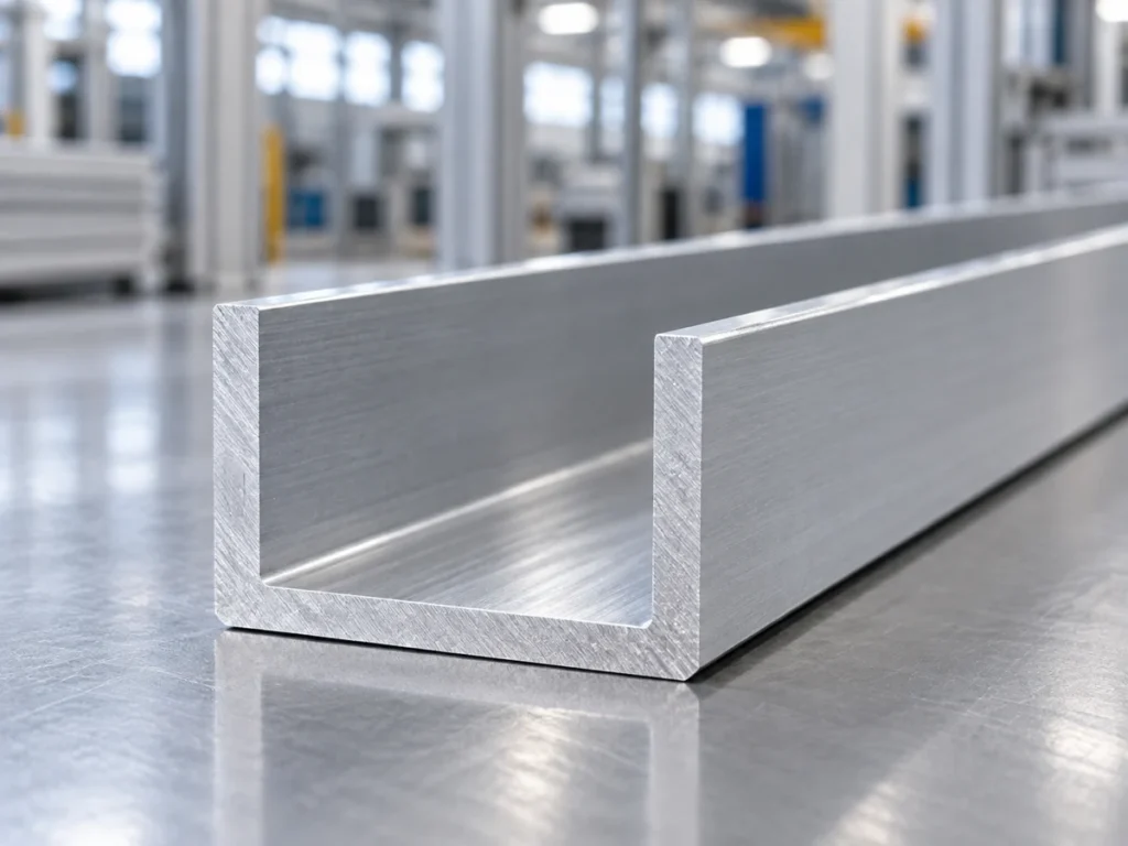
Keep a plain U-channel separate from the mounting rail requirement. Its cross-section may be useful for another mechanical purpose, but a channel photograph does not establish the intended mounting interface. Ask for the exact section rather than the closest-looking stock image.
2. Define the cut length and measuring faces
Put the finished rail length on the component drawing or approved cutting list. Define the two end faces used for measurement, the units and the applicable tolerance. Keep the reference consistent across the quotation, order and inspection record.
Separate the purchased stock length from the length of each required piece. If the buyer supplies stock, record its identity and condition. If the supplier provides stock, require confirmation of the approved product before evaluating the cutting plan.
A cabinet’s outside width is not automatically the rail length. The assembly drawing must define the available mounting space and any required clearances. Procurement should transfer the approved component length to the order instead of deriving it from an overall cabinet dimension.
For mixed lengths, assign a separate part identity to each row. Include the required accepted quantity and drawing revision. Our finished-length datum guide explains how to keep the measuring reference clear when several drawings are involved.
3. Keep mounting holes and end positions visible
State whether the ordered rail is perforated, unperforated or separately drilled after cutting. Attach the relevant pattern drawing. A description such as “with holes” does not define the mounting layout.
For perforated stock, identify any required relationship between the final cut end and the holes or slots. The cutting list’s length field alone cannot communicate that relationship. Let the approved drawing specify the acceptable end region and feature references.
For an unperforated rail that needs later holes, assign that operation explicitly. Define who supplies the machining drawing and who checks the resulting features. The hole-position guide covers the separate datum and inspection fields.
Do not infer a hole pattern from a different catalog version. Check the exact product and drawing used in the order. The person reviewing the quote should be able to distinguish a standard perforated item from a blank that requires additional processing.
4. Agree the cut-end checks before releasing the batch
List the cut-face and edge requirements in the purchasing documents. Refer to the specified length, end-face condition and any required finishing step. Avoid a broad instruction such as “clean cut” when the buyer expects a measurable or separately processed feature.
Ask the proposed cutting supplier to review the actual profile and its support requirements. Provide representative stock or a controlled section drawing. A photograph of a larger channel does not demonstrate how a thinner mounting rail will behave in a proposed setup.
If a sample review is required, tie it to the product identity, drawing revision and supplied stage. Record what was checked and which questions remain with the assembly team. A sample should resolve defined requirements rather than serve as a general promise for every later profile.
Use the deburring and chamfer guide to separate edge cleanup from a dimensioned chamfer. The accepted edge condition must come from the applicable requirement; this article does not prescribe a universal chamfer or a cutting setting.
5. State what the supplier actually delivers
Describe the supplied stage in plain words: identified stock, cut rail blanks, processed rails or installed assemblies. List the included operations and the remaining work. This keeps two quotations comparable even when their scope differs.
Assign packaging and identification requirements to each part. Keep different profiles and lengths in separate labeled groups. State how held pieces will be separated from released items so that an unresolved component is not counted as ready for assembly.
Keep electrical function, mounting approval and any required product evidence with the responsible design or assembly owner. A cutting quotation and a neat end face do not establish electrical ratings, protective-conductor suitability or acceptance of the completed cabinet.
A fictional purchasing example
Consider fictional cabinet project R27, revision B. The approved list calls for 24 cut pieces of one identified unperforated rail, each 420 mm long. The assembly owner has a separate mounting-hole drawing. These invented order details illustrate scope control; they are not a supplier offer or a recommended cabinet design.
| Fictional quote response | Question before acceptance |
|---|---|
| Correct rail identity; 24 cut blanks at 420 mm. | Confirm cut-end requirements and whether later holes are excluded. |
| Same nominal width; different rail depth. | Send the proposed substitution to the assembly owner. |
| Perforated rail offered instead of the specified blank. | Check the exact pattern and approved component requirement. |
| “Ready to install” without an operation list. | Request the included processing and acceptance scope. |
The useful comparison is the confirmed identity and delivered stage, not just a price beside “420 mm rail.” Record any approved change in the controlled documents before releasing the order. An informal description in an email should not silently replace the component drawing.
Send a usable cutting inquiry
Send the exact rail designation or section drawing, cut list, quantity, material condition and supplied-stage requirements. Add the end-to-hole references where relevant, the required edge condition and the next operation. Identify the responsible person for any open assembly question.
Use JiurunCut’s contact page to request a cutting review of the actual profile. Ask the supplier to confirm its scope and the information needed for a representative review. Keep any later machine recommendation tied to that review instead of assuming capability from a generic cabinet image.
Buyer questions
Are all 35 mm rails the same?
No. The cited examples share a nominal width but differ in depth and perforation. Identify the full product and approved mounting interface.
Can a U-channel replace an aluminum DIN rail?
Do not approve a replacement from appearance alone. Send the proposed section and component requirements to the responsible assembly owner.
Does a cut length define the mounting-hole positions?
No. Put the required hole or slot references on the applicable drawing, including their relationship to the cut ends where needed.
Does this guide qualify the rail for an electrical function?
No. It organizes purchasing and cutting information. Electrical and assembly acceptance require the applicable design requirements and evidence.