
Aluminum burr direction after sawing is a part-acceptance question, not a promise that every saw will put a burr on a chosen side. If one edge enters a tight joint, visible face, seal, or sliding interface, identify that edge on the released drawing and check the actual cut parts. A useful saw RFQ asks which edges may retain material, how those edges will be inspected, who removes an unacceptable burr, and what evidence releases the first batch. This is a different decision from asking only for a maximum burr height.
For a mixed profile portfolio, the answer can change with wall geometry, blade condition, support, orientation and the exact cut. Treat an anticipated burr side as a trial hypothesis until samples from the quoted process confirm it. Do not reverse stock or change a guarded machine setup simply to move a burr without the machine builder’s approval and a new first-off check.
1. Define aluminum burr direction at the assembly-critical edge
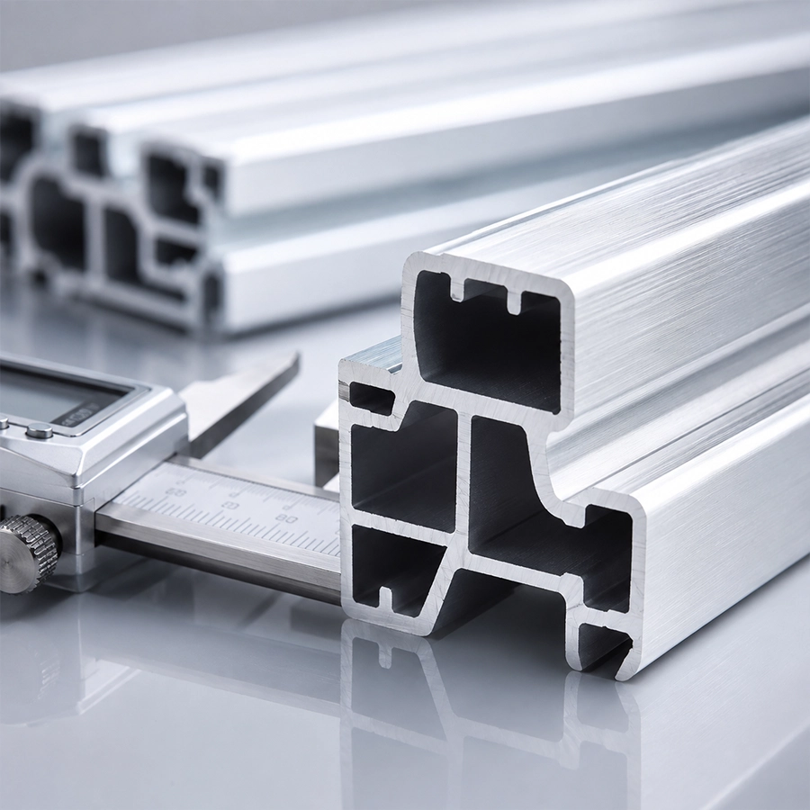
Start with the receiving part, not the blade. On a section drawing, mark the functional face, visible face, locating face and cut-end edge that contacts the next component. State whether the requirement applies to the left end, right end or both. For a mitred member, add the installed orientation and the mating part. A note saying “burr-free” cannot tell the supplier which edge affects the assembly, how it is checked or whether a separate finishing step is included.
Give each relevant edge an identifier, such as E1 at the visible outer lip and E2 at the mating inner wall. A photograph of a marked first-off sample can accompany the drawing, but the drawing and revision remain the authority. If a thin wall or internal slot cannot be reached by the proposed gauge, agree on a feasible inspection method before a quote is accepted.
2. Distinguish the two ends and the two sides of one cut
A cut produces a retained part and an offcut or next-stock end. The two ends may have different roles. The finished piece could be inspected for a mating edge while the remnant needs safe handling and a usable next datum. State which physical side is the accepted product, especially when a stop, feed direction or part-transfer device makes the words “left” and “right” ambiguous. Use a marked sample or a sketch that shows the saw infeed direction, operator view and finished-part direction.
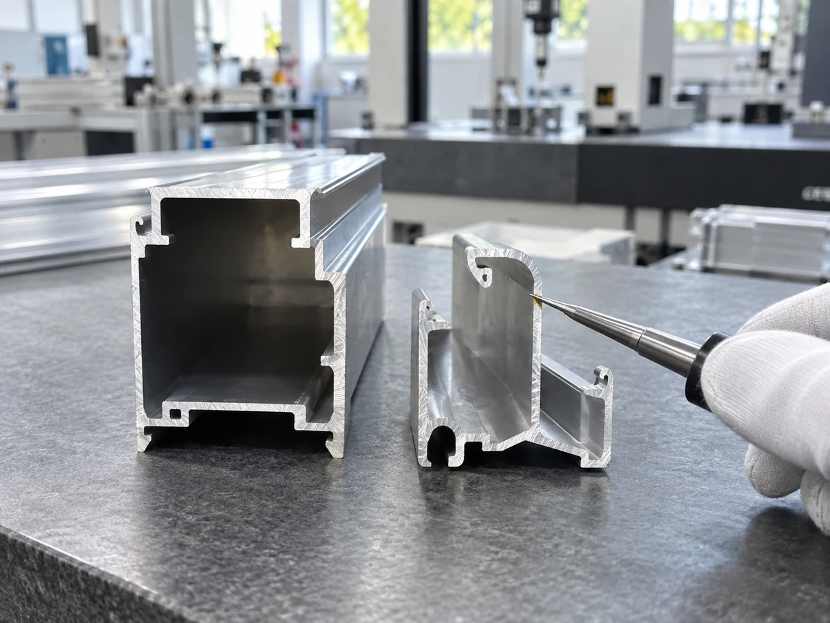
Then inspect the external lip, internal wall and any extrusion ribs that matter. A single top-view photograph can miss a raised edge within a hollow section. A pass on one face is not a pass on every face. Where appearance matters, inspect under agreed light and viewing conditions; where fit matters, test the actual mating or gauging condition. Do not substitute an attractive cut-face photograph for the assembly test.
Research on burr formation in orthogonal cutting of an aluminum alloy and face milling of aluminum alloys shows that exit geometry and conditions can affect burr formation. Those studies are not a qualification of a Jiurun circular saw or a recipe for a specific profile. They support the practical decision to identify and test the relevant edge on the actual sawing route.
3. Specify a representative first-off trial
Send the supplier the approved alloy and temper, section drawing, wall range, straightness condition, stock length, cut length, angle and required part orientation. Include the most delicate and the most reinforced profiles if one saw must cover both. Tell the supplier which blade, clamp or support configuration is quoted and which variants require a change. An attractive demonstration on an easier extrusion does not settle the burr question for a narrow lip or an interrupted wall.
Ask for first-off samples at normal production handling, not only a carefully selected best cut. Keep the actual blade identity and condition, cut settings, stock lot, clamping and support arrangement, and whether lubrication or chip removal was used. Record which part came from each end of the trial bar. If settings change to improve one edge, repeat the accepted-part checks for length, squareness and the other critical edges. A reduced burr at one lip does not excuse a new defect elsewhere.
For safety, any access to the blade or guarded work zone for inspection, cleaning or adjustment must follow the machine’s approved procedure. A buyer can require an observable trial and traceable records without prescribing unsafe access or unsupported machine adjustments.
4. Agree how the result is judged and handed off
The receiving team should choose a measurable criterion for each critical edge. Depending on the approved drawing, this may be a specified maximum projection, a no-interference mating test, an agreed visual standard, or a required deburring operation followed by reinspection. Avoid inventing a universal “acceptable” burr value: it depends on the part and downstream operation. If a limit is in a drawing, identify the gauge or method, where it contacts, how samples are selected and who signs the result.
| Buyer question | Evidence to request | Scope boundary |
|---|---|---|
| Which edge matters? | Released drawing with marked edge and installed orientation | Product design and assembly criteria belong to the buyer or OEM |
| What does the saw deliver? | Marked first-off parts from the quoted stock, blade and setup | A saw trial proves only the tested process and materials |
| Who removes a residual burr? | Quote line for deburring, inspection and accepted-piece handoff | Do not assume edge finishing is included with the saw |
| What restarts a held job? | Revised setup record and fresh accepted first-off result | Blade, stock or support changes need the agreed release rule |
If the saw-cut part is a blank for later machining or finishing, say so. The buyer can accept a controlled residual edge at the blank stage if the next operation is specified and owned. If the cut part goes directly into a visible joint, the acceptance may be tighter. Compare quotations at the same accepted output stage rather than treating saw-only and saw-plus-deburr prices as equivalent.

5. Write the burr-orientation question into the RFQ
Ask the saw supplier to describe the actual part path: stock presentation, datum, clamp support, blade and finished-piece removal. Request a trial matrix covering each profile family and both critical ends. If the supplier proposes a different orientation to protect an important edge, ask what else changes: feed presentation, stop reference, cut angle, handling, cycle and first-off checks. Do not infer a guaranteed burr position from blade rotation alone. It has to be observed on the proposed configuration.
When comparing alternatives, separate three routes: accept the saw-cut edge as produced; add a defined manual or automated deburring operation; or buy a finished part or prepared kit from a qualified supplier. Each route should carry the same receiving definition, inspection evidence and responsibility for rejected pieces. For a broader equipment choice, see our sawing and deburring line comparison. For the separate question of how much projection is acceptable, see the aluminum burr height inspection guide. Confirm the final URL and criteria on the released documents; an internal article is background, not an acceptance specification.
Related equipment video
The following Jiurun Machinery channel video is a related aluminum saw equipment demonstration. It does not show this article’s edge map, stock lot, blade setup, customer part, burr-direction test or performance result.
RFQ package to send
- Released section and cut-part drawings, revision, material and stock condition.
- Marked functional, visible and mating edges for each finished end.
- Quantity and job mix, including the difficult thin-wall or reinforced profiles.
- Required accepted output stage: saw-cut blank, deburred blank or finished kit.
- First-off sample, inspection method, acceptance limit and sign-off owner.
- Proposed blade, support, handling and changeover record for the actual trial.
Need a saw quote for a mixed aluminum profile job? Send JiurunCut the drawings, marked critical edges and representative stock details. We can discuss a suitable saw-cut trial and quote boundary; your team retains approval of the part drawing, downstream edge treatment and final assembly acceptance.