
Aluminum frame connectors can change the cuts and preparation each frame member needs. In your saw inquiry, link the connector part ID and preparation document to the current member drawing. Mark end A, end B and the length reference. Ask what the saw must produce, what additional machining is specified and who is responsible for each stage.
For a machine purchase involving aluminum frame connectors, the question is: What can the quoted equipment produce, and what work must happen elsewhere before this member is ready for its connector? Request an operation-by-operation response rather than accepting “frame production” as a complete scope description.
Table of Contents
Link aluminum frame connectors to each member drawing
Start with the assembly drawing, but attach a separate specification for every affected rail or upright. Identify the aluminum frame connectors at each joint and link each one to the relevant member end. Do not assume that both ends of a member use the same connection or need the same preparation.
On the member drawing, mark end A, end B, their required cut geometry and the endpoints or reference surfaces defining length. Where the connection changes, have the design owner identify which requirements change and which remain valid. Keep the assembly dimension and the loose-member dimension separately identified. If later machining changes a controlled dimension, ask the design owner to define the saw-stage requirement separately from the final-member requirement; do not assume the same value applies to both stages.
On drawings involving aluminum frame connectors, identify the component carrying each hole, recess or thread callout: the purchased connector, the aluminum member or another part. A hole shown in connector hardware is not, by itself, an instruction to drill the profile. Request the applicable profile-preparation drawing instead of inferring it from an assembly photograph.
Use the mitered-part length reference guide for the separate question of which points define an angled member’s length. This inquiry should record the approved reference against the connector and member revision, not invent a new length from the joint’s appearance.
Compare preparation requirements for aluminum frame connectors
An external bracket with no machining required for that fastening method
80/20’s 30-4302 inside-corner bracket is described as an external fastening method requiring no machining services. Limit that statement to the specified fastening method. Keep the member’s required end cuts and any unrelated drawing features in the inquiry.
A miter connector requiring cuts and additional profile preparation
80/20’s 13193 miter connector specifies miter cuts on both profiles and counterbores in the mounting and mating profiles. Record the end cuts and counterbores as separate requirements rather than putting everything under “miter cutting.”
These are product-specific examples of aluminum frame connectors, not interchangeable recommendations. Confirm compatibility and the current preparation drawing for your chosen part. Neither description establishes that a JiurunCut saw performs the additional machining.
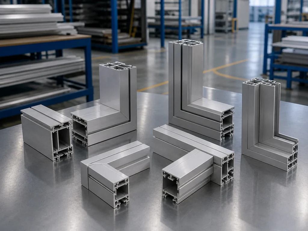
Keep a connector-to-member revision map
Use a comparison record with these fields: assembly drawing and revision; connector part ID and preparation-document reference; member ID and drawing revision; affected end or feature; required operation; responsible party; quotation revision and response status. Record the connector document revision or issue date where available; if neither is shown, record the source and access date and ask the supplier to confirm the applicable issue.
Create a separate entry for each affected end or operation. “Scope owner” means the named party responsible for that item in the proposal. Distinguish equipment supply, production work and inspection responsibilities when different parties handle them. Keep the drawing approval owner identifiable too.
A revision to aluminum frame connectors should trigger a review, not an automatic change to every cut length. Have the design owner mark each member as changed, unchanged after review, or still undecided. Retain the superseded reference so the supplier can explain which proposal lines need updating.
Fictional comparison: a revised connection on one rail
The following is an invented purchasing example, not a customer case, tested assembly or substitution between the two 80/20 products above. All DEMO identifiers and requirements are fictional. Connector suitability remains a separate design decision.
| Record field | Earlier proposal | Revised proposal for review |
|---|---|---|
| Assembly drawing | DEMO-FR, revision A | DEMO-FR, revision B |
| Connector and preparation reference | DEMO-EXT; fictional preparation note A | DEMO-INT; fictional preparation note B |
| Finished member ID | DEMO-RAIL-01, revision A | DEMO-RAIL-01, revision B |
| End A and end B | Both square, as defined in the fictional drawing | Both mitered in this fictional drawing; direction and references awaiting release in revision B |
| Length reference | Marked span between the square end faces | Marked outer-tip span; required value still awaiting design approval |
| Connector preparation | No added profile machining specified for this fictional scheme | Counterbores specified at both ends; locations and acceptance requirements still pending |
| Scope owners | Equipment supplier: saw proposal. Buyer: cutting production and member inspection. | Same saw responsibilities proposed; buyer’s machining department must confirm counterbore work. Buyer design engineer owns drawing release. |
| Quotation reference | DEMO-Q, revision A: saw scope only | Request DEMO-Q, revision B, with changed cuts and separate machining responsibility |
The next action is not to reuse the old cutting list. Request the approved revision B member drawing, ask the equipment supplier to reassess its saw scope, and obtain the machining department’s response. The unapproved length and counterbore details remain open; they are not instructions for production.
Both ends change here because the fictional drawing says so. On a real job, record each affected end or feature separately and leave unrelated members unchanged after review. For release, affected quantities and earlier pieces, use the cut-list revision control guide.
Separate saw output from connector-ready output
Keep the finished member ID on the records for each process stage. Add a clear stage description, such as “after sawing” or “after connector preparation,” so a saw-stage piece is not mistaken for an assembly-ready member.
Ask the supplier to answer each applicable line below. Mark the commercial scope as included, separately quoted, buyer-provided, excluded or undecided. Also record whether the technical requirement is confirmed, an exception or still to be reviewed. A missing answer is unresolved, not proof of capability or incapability.
| Scope line | Required definition | Responsibility to identify |
|---|---|---|
| Saw-stage end cuts and length | Member revision, end A/B geometry, marked length reference and checks at the saw-output stage | Who supplies the proposed cutting equipment, who operates it in production and who accepts the saw-stage output |
| Connector-related holes or counterbores | Each required profile feature, its drawing reference and the preparation document it follows | Which equipment or service covers it, who performs it and whether it is inside or outside the equipment quotation |
| Milled features or tapped threads, if specified | Only the features required by the actual drawing; do not add them merely because a connector is present | The responsible process provider and inspection owner; no assumption that these functions belong to the saw |
| Deburring or other finishing, if specified | The required output condition and whether acceptance is before or after that operation | Who performs the work and which quotation or buyer process covers it |
| Connector fitting and assembly checks | Connector ID, member revisions, agreed fit criteria and process stage being assessed | Who supplies the hardware, assembles the joint and records the result |
For members using aluminum frame connectors, equipment supply is not the same scope as an ongoing part-machining service. State which you are purchasing. A quotation for a saw should identify the equipment and output it covers, without implying that the seller also supplies finished, drilled or assembled frame members.
For the broader machine-selection and support/clamping discussion, use the aluminum cutting machine buying guide. Keep the connector-linked operation and ownership decisions in this member record.
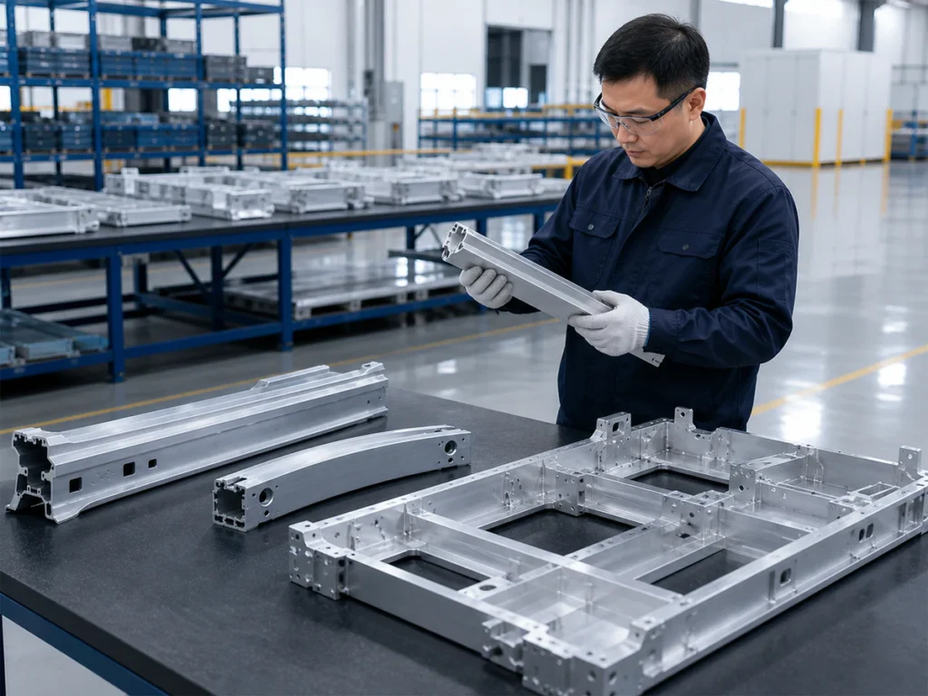
Tie any demonstration to the operations it actually covers
When requesting a sample review, link the specimen to the connector ID, member revision and process stage. Ask which operations produced it, on which equipment, and who carried out any work outside the proposed saw configuration.
If a sample was machined elsewhere after sawing, keep those stages separate in the report. Do not treat the assembled joint alone as evidence that the saw performed every operation. For general trial planning, use the sample-cutting trial checklist; the extra requirement here is traceability to the connector-preparation scope.
Use the aluminum corner cutting machine page as an equipment discussion reference. Request a configuration-specific response for your members; the model name and reference media do not confirm connector-machining functions.
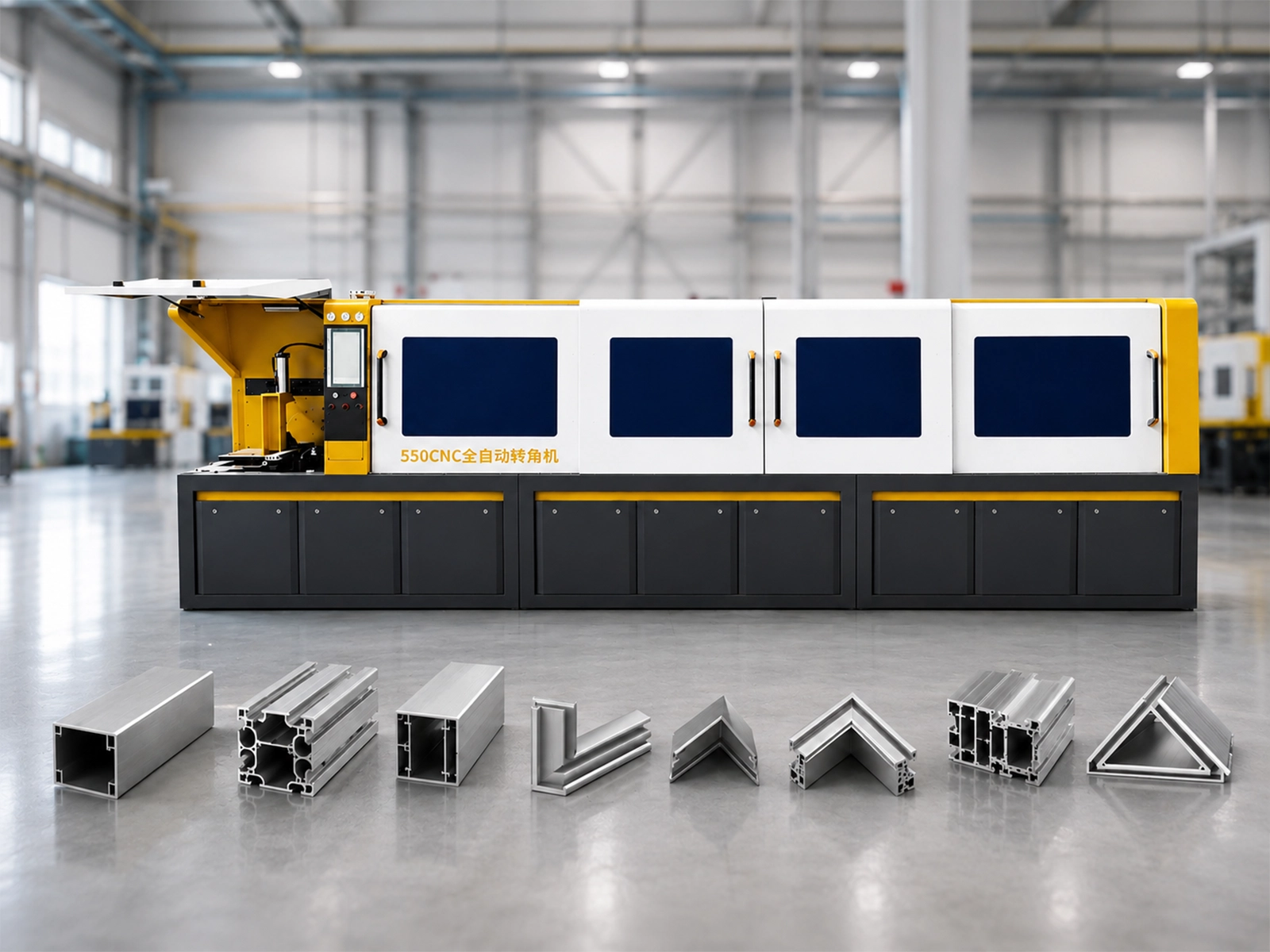
Video reference for the equipment discussion
Reference video only. Do not use it as acceptance evidence for connector preparation; request records identifying the actual parts, equipment and operations assessed.
Open the reference video on YouTube
Make undecided items visible before comparing offers
Record whether the selection of aluminum frame connectors is provisional, which member drawings await release, and whether the length reference or preparation features are still changing. Name the person responsible for each decision and identify which proposal lines depend on it.
Separate “no extra machining required for this approved connection” from “connector preparation not yet specified.” The latter remains an open item, not an exclusion or an accepted saw-only solution.
For a revision, request a response against the affected member IDs and ends: revised saw scope, unchanged scope after review, separately required work and remaining exceptions. Compare offers only after identifying whether they cover the same member revisions and output stages.
Copy a connector-scope request
This buyer template turns the records above into a request for a written response. Replace bracketed prompts with your references. The example reply labels below describe review stages; they are not an actual supplier response, approved configuration or JiurunCut commitment.
Please review [package reference and issue date], including the connector preparation documents and member drawings listed in its attachment register. We are requesting a cutting-equipment proposal. Our workshop’s intended responsibilities and undecided items are marked in the scope record.
Please identify the files and revisions received. Flag missing attachments or conflicting references before using this package to assess the affected members and ends. Receipt of the files alone should not be recorded as confirmation of equipment suitability.
Return a response against our marked scope lines. Identify what has been reviewed, what remains under configuration review and which information or decision is still needed. For additional preparation, name the proposed equipment or service and the party expected to perform and inspect it.
In your quotation, reference the package reviewed and identify included equipment, separately priced items, buyer-provided work and exclusions. Keep unanswered items open. If a revised drawing changes your response, identify the affected quotation lines before we compare the offer.
Read a reply according to its stated scope:
- Files received: the attachment register is acknowledged; technical suitability is still unconfirmed.
- Configuration review pending: identify the open requirement, information owner and next decision. A proposed setup remains subject to that review.
- Quotation scope stated: check the quoted revision and each named responsibility against your request. Included equipment does not mean the supplier has accepted ongoing production or inspection work.
Discuss aluminum frame connectors and member revisions with JiurunCut
Share your current profile section, material and selected aluminum frame connectors. Include their part IDs and preparation documents, plus the assembly and finished-member drawings with revisions. Mark end A and end B, the required length reference and any additional features.
Tell us which work your workshop will handle, which equipment scope you want reviewed, and who owns the remaining preparation. Include undecided fields and planned changes rather than treating a provisional design as final.
Discuss My Connector and Member Requirements
Start with the information you have and mark missing documents as unresolved. Ask for the saw-stage output, additional operations and responsible parties to be identified against the same drawing package.
Use this guide to prepare an inquiry for cutting members that use aluminum frame connectors. Connector suitability and the operations in the purchased configuration require separate confirmation against your drawings.