
Different-width aluminum profiles can meet at a miter corner when the joint is designed for those two sections. The two end slopes may need to differ even when the assembled corner is square. Look at both members together before choosing the cutting setup.
On this page
Different-width aluminum profiles: two widths, one corner
Imagine looking down at two flat, straight members that turn a square corner. Their depths are compatible, and the design calls for the inside and outside borders to meet neatly.
Mark where the two outside edges meet. Then mark where the two inside edges meet. In this simple outline, the straight meeting line runs between those two points.
With equal widths, the arrangement is symmetrical. With different widths, the inside corner moves relative to the outside corner. The meeting line changes direction, so it makes a different slope against each member’s long edge.
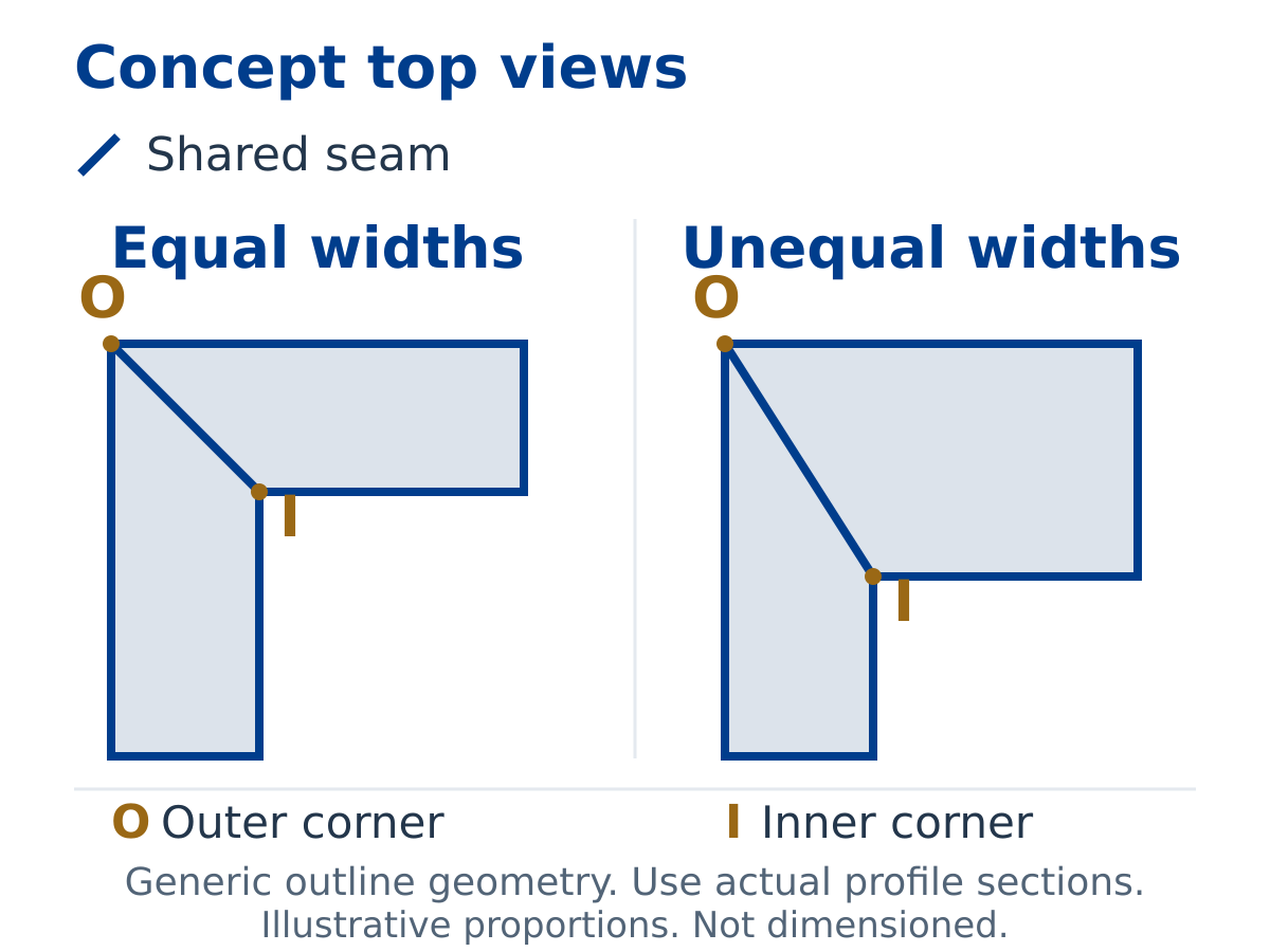
The width here is the width visible in the corner view. It is separate from the wall thickness or depth of the extrusion. Show how the different-width aluminum profiles sit in the frame when identifying these widths.
Show us the two members together
Share the assembled corner view and both profile sections. Tell us which borders need to line up.
Look beyond the outline
A simple outline explains the meeting line, but an extrusion also has its own features. A groove, lip or internal web can reach the end differently from the outer border. Two profiles may look aligned from above while their side faces or connecting features still need attention.
Show the actual section drawings and the intended connector. If a panel sits in the frame, include its relationship to both members. The chosen joint and connector still need to suit the application; a neat outline alone does not establish that.
Our butt-versus-miter joint guide discusses connectors and the complete assembly route.
A wider rail and a narrower upright
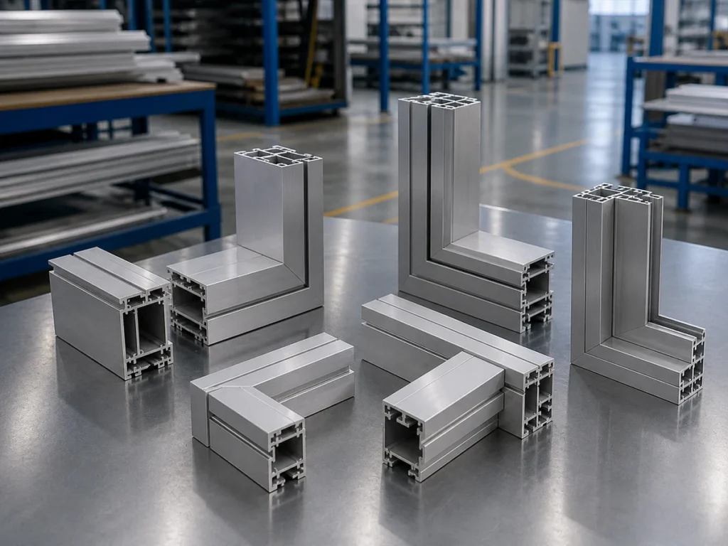
Suppose a workshop changes an equal-width frame design to use a wider bottom rail and a narrower upright. The finished frame still has a square corner, but the two members no longer have the same width in that view.
Copying the old matching end slopes may leave part of one end exposed or create an unwanted step. The supplier should check the new pair as one corner, including where the inside and outside borders must meet.
Keep each member’s finished length tied to its own drawing reference. Changing an end slope also changes where its tips lie. See the miter cut-length guide for long-edge and short-edge references.
Watch: Jiurun angle-saw demonstration
Use this machine reference when discussing your proposed pair of angled ends.
Planning repeat corner parts?
Send both sections, the finished corner view and the quantities for each member.
Discuss the cutting arrangement
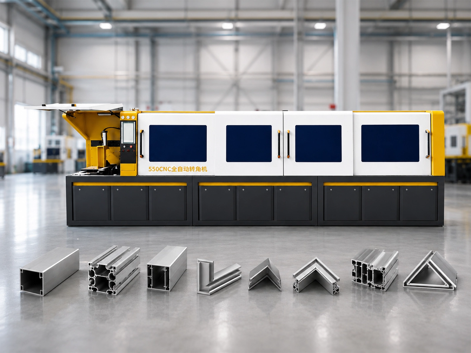
Jiurun’s brochure presents the JR-550CNC-CORNER with automatic feeding, positioning and cutting. It is a machine reference for discussing angled profile work. Ask Jiurun to check both actual profiles and their finished ends against the proposed configuration.
Once the joint geometry is clear, the discussion can cover how each member will be supported, held and cut. Ask for the proposed setup for each part, rather than assuming that one arrangement covers both.
Which cutting setup fits your corner?
Share your different-width aluminum profiles and the corner you want to make. Jiurun can discuss the machine proposal around those parts.
Sources and scope
Machine context: Jiurun machinery brochure, physical PDF page 13, available through Catalog & Downloads. The diagram is an original, simplified flat-strip top view with a square corner and compatible depths. Actual section features, connectors and machine suitability need their own review.