
Aluminum butt vs miter joints change the corner geometry, cut-length references and connector requirements of a frame. In this comparison, a butt corner uses a square-ended member meeting the side of another member. A miter corner uses angled ends meeting at the corner. Choose the joint together with its approved hardware and assembled dimensions.
Neither shape establishes strength by itself. Profile geometry, the connector and the complete application need their own design review. Four decisions help buyers compare the options before releasing a cutting list.
Start with the assembled frame
- Show which member runs through each corner.
- Specify the actual connector and its access requirements.
- Derive the cutting list from the approved joint geometry.
On this page
Aluminum butt vs miter joints at a glance
Use the terms with a drawing. Suppliers also use “butt fastener” for an end-to-end splice along one straight line. That is a different geometry from the square-ended corner described here. A product name alone is not enough to specify the assembly.
| Corner arrangement | What to define |
|---|---|
| Square-ended butt corner | The through member, the member meeting its side and the approved connector. |
| Miter corner | The angle at each end, profile orientation, meeting faces and the approved connector. |
| Either arrangement | Assembled dimensions, access, finish, functional requirements and acceptance criteria. |
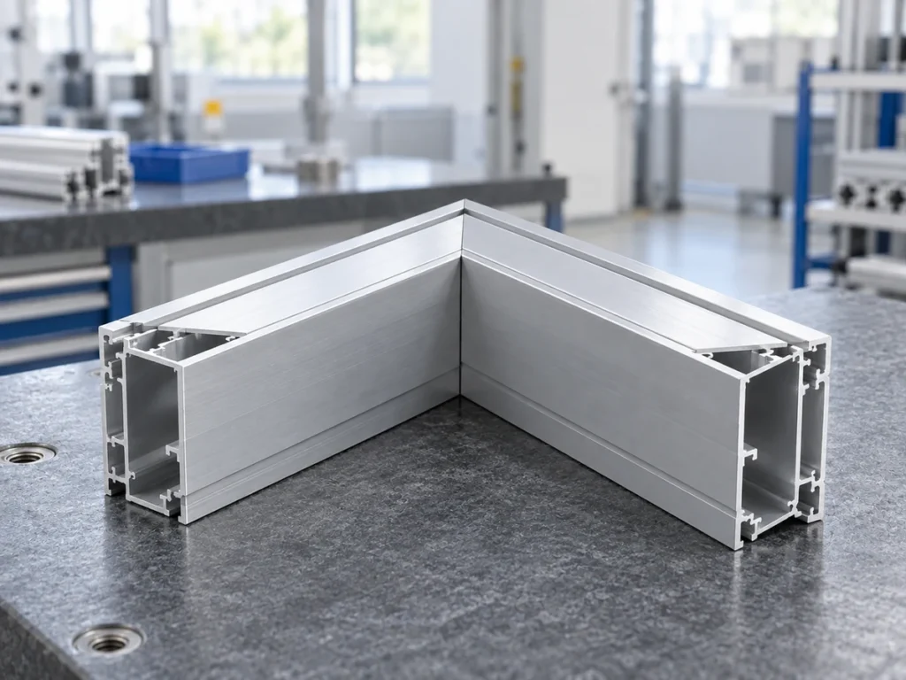
Decision 1: Define corner geometry before member length
Draw the assembled frame and identify every member. In a square-ended butt corner, show which member continues through the corner and which terminates against its side. Reversing that relationship can change the individual part lengths even when the outside frame dimensions stay the same.
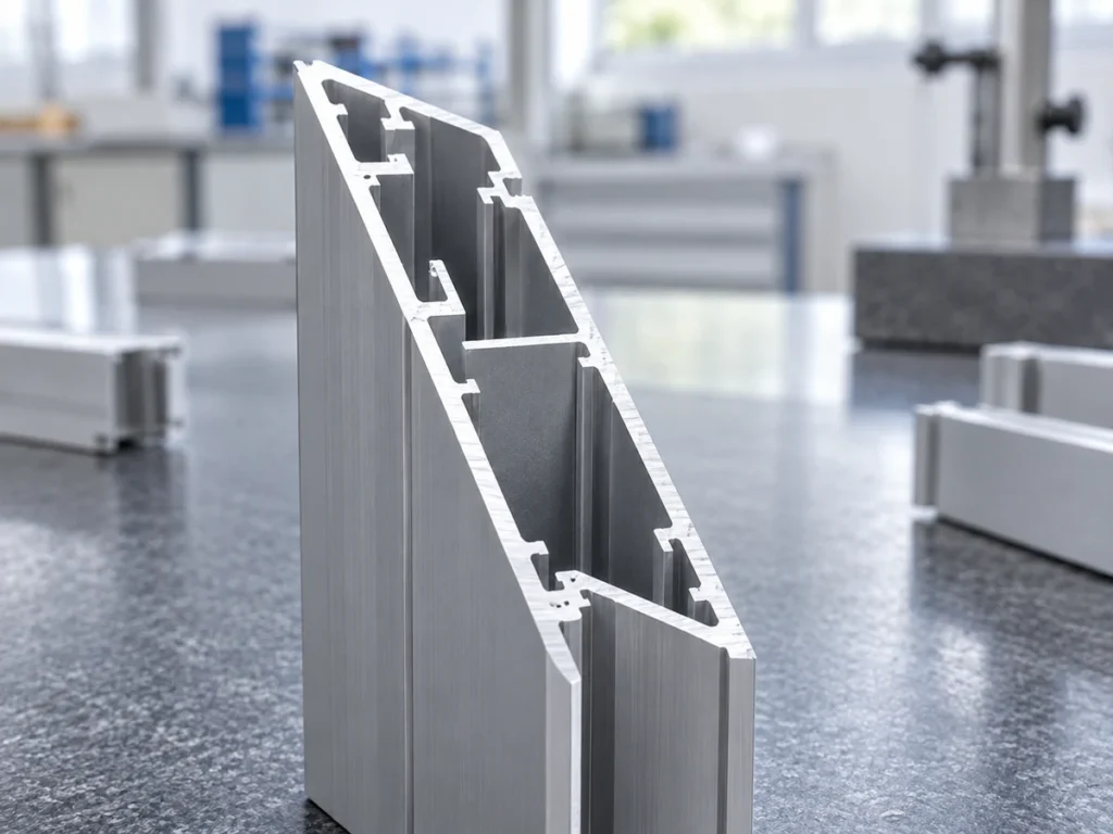
For a miter corner, identify the finished angle and the length reference. Show whether a member length is measured between long points, short points or another specified reference. Keep the cut plane and the profile’s installed orientation visible.
Our miter cut-length guide addresses those references in more detail. The key purchasing step is to derive the parts from the approved assembly, rather than using one cut list for two different corner designs.
Make the opening dimension separate from the overall frame dimension. A panel, cover or mating assembly may depend on the opening, while an installation envelope depends on the outside. Record both when the application requires them.
Keep handed parts distinguishable
An asymmetric profile can look correct as a loose part while facing the wrong way in the frame. Mark the visible face, panel groove or relevant feature. Use part identities for mirror versions instead of expecting the assembly team to infer the orientation from the angle alone.
80/20’s Tech Toolkit includes a miter worksheet and design tools. That illustrates the value of a defined drawing and calculation workflow. It does not replace approval of the specific frame and its cut-length references.
Decision 2: Select the connector and check access
Identify the connector by its approved specification. Confirm the profile family, groove or bore relationship and required preparation. A connector that fits another profile with a similar outside size may still require different features.
The item fastener overview distinguishes right-angled connections, colinear butt connections and miter connections. These are different arrangements with different fastening options. Keep the chosen product linked to the joint shown on the drawing.
Ask where the installer must reach the fastener. Check whether a panel, adjacent rail or finished cover blocks that access. Include assembly and future disassembly in the review if the application requires both.
Confirm whether the connector needs holes, threads or other profile preparation. Show those features in the controlled drawing package. A quotation for cut pieces alone should not be mistaken for a complete set of connector-ready components.
Review substitutions as a joint change
Changing hardware can change preparation, access and the assembled relationship. Ask the supplier to identify the exact proposed substitution and any drawing changes it requires. Obtain approval before cutting or machining parts to the revised geometry.
For slot-based hardware, the T-slot nut compatibility guide helps organize the interface checks. A matching nominal slot label alone should not replace the supplier’s confirmed component definition.
Decision 3: Separate appearance from frame function
Describe the visible corner that the customer expects. Which faces will be seen? What meeting-line appearance is acceptable? Are exposed profile ends or connector caps part of the approved design? Give the supplier a drawing or agreed visual reference for those questions.
A miter can create a continuous-looking corner, but that appearance is not proof of load capacity. A square-ended corner also requires an approved connector and application review. Avoid choosing a joint from a photograph that omits its hardware and loading conditions.
For a concrete example, item’s Mitre-Fastening Set description includes application restrictions and cautions for its particular connection. Those limits belong to that product. They should not be converted into a universal rating for every aluminum miter joint.
Have the responsible designer establish the structural and other functional requirements of the actual frame. If the frame retains a panel, also confirm how the panel is supported and how its edges relate to the chosen corner.
Specify what the first assembly must demonstrate
A review may cover outside dimensions, opening dimensions, visible corner fit, hardware access or an approved functional requirement. State the scope in advance. Do not let an attractive corner become a substitute for checks that the application still requires.
Where a rectangular frame has a diagonal requirement, connect it to the frame diagonal check. Keep that measurement separate from individual member length and the local meeting line at a corner.
Decision 4: Compare the complete manufacturing route
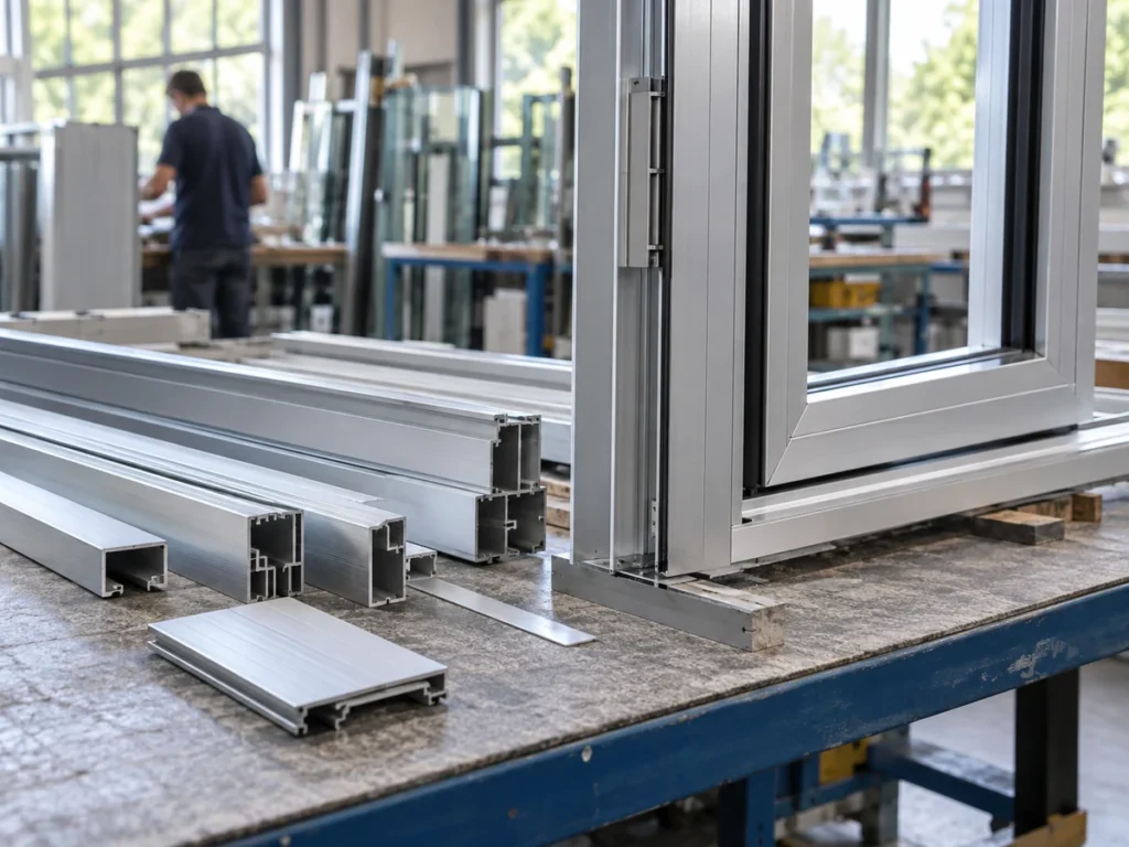
List the operations each approved option needs: cutting, connector preparation, edge treatment, finishing, identification and assembly. Compare quotations for the same scope. An option with a lower cutting price may have a different downstream preparation requirement.
Ask the supplier to distinguish included operations from proposed or excluded work. Record who performs each step and which drawing revision controls it. Avoid claiming that one corner shape always produces lower cost or faster output.
Review handling of finished surfaces and angled points. Name the agreed edge condition and packaging requirement rather than applying an unapproved edge break everywhere. Protect the features that the joint relies on.
If an assembly will be delivered as a kit, tie the labels and quantities to the frame-kit cutting plan. The correct parts still need to arrive in a form that the customer can identify and assemble.
A useful comparison exercise
Illustrative planning example: a team considers two corner layouts for the same frame envelope. Option A uses square-ended members meeting side faces. Option B uses mitered ends. It creates separate assembly drawings and cut lists for the two options.
The team then requests connector specifications, required preparation and assembly-access information for each layout. It compares the complete approved route, not just the number of saw cuts. This is a fictional exercise and includes no measured cost, output or load result.
Release the cutting requirement
Before ordering, provide the assembled drawing, member identities, profile section and orientation, end geometry, length references, quantities and relevant connector preparation. Keep any unresolved joint question visible until the responsible team approves it.
For a JiurunCut cutting inquiry, send the profiles and controlled cutting requirements. Include both square and angled parts where the frame requires them. The cutting proposal should follow the approved geometry; connector and frame-performance approval remain with the responsible design parties.
Buyer questions
Does “butt fastener” always mean a square-ended corner?
No. The term can refer to a colinear end-to-end connection. Use a drawing and the exact connector definition to remove ambiguity.
Can the same cut list be used after changing the corner design?
Recheck it against the revised assembled geometry. Member relationships and length references can change.
Is a miter joint automatically stronger or weaker?
Review the actual profile, connector and application. A joint label alone does not establish a rating.
What makes two quotations comparable?
Use the same approved assembly requirements and compare cutting, preparation, finishing, identification and assembly scope together.