
Die casting ejector pin bosses should be reviewed as identified features on the component drawing. Locate each proposed contact area, name the supplied surface condition and connect it to the finished part’s interfaces. That gives the foundry and designer a specific feature to discuss.
For an aluminum housing project, the useful question is where the proposed feature belongs and what the delivered component must look like at that location. A general note such as “good finish” leaves both questions open.
On this page
What die casting ejector pin bosses describe
Dynacast’s design-for-manufacture FAQ explains that ejector pins push the casting from the die after it solidifies. Ejector pin bosses are reinforced local areas where the pins contact the part. Its discussion treats those areas as features considered during component design.
The manufacturer’s engineering overview also identifies boss placement and a slight indentation as design considerations. Those statements explain the feature’s context; they do not supply a universal boss dimension or an acceptance limit.
Start with the foundry’s actual proposed geometry. Ask it to identify the relevant faces and features on the current model. Keep the designer’s finished-part requirements beside that proposal.
Our casting draft-angle guide addresses another ejection-related geometry question. Draft and a local pin-contact feature need their own identified descriptions.
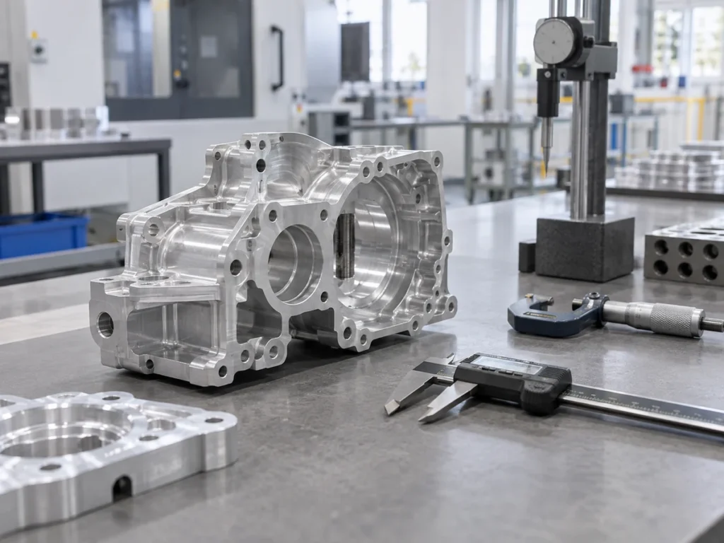
Check 1: locate the feature in a recognizable view
Give the reviewer a drawing view that makes the proposed contact area easy to find. Add its feature identifier and show the relevant face. Use a section or detail view when the external view hides the relationship.
Keep the proposal’s location reference with its dimensioned geometry. “Inside the housing” may describe several different faces. A feature such as EP1 can be connected to a particular view and model revision without relying on a verbal description.
Show the neighboring interfaces that the design team needs to review. These might be an identified mating face, attachment area or required internal clearance. Use the actual part’s controlled requirements rather than treating every nearby surface as interchangeable.
If the foundry proposes another contact position, request a marked comparison. The reviewer should be able to recognize the old and proposed arrangements and see which component definition changes.
The purpose of these views is a clear technical discussion. Pin selection, positioning and ejection-system design remain project-specific engineering work for the responsible foundry and designer.
Check 2: identify the required final surface
Label whether the relevant area is supplied as cast, processed later or subject to a specified finishing operation. Connect that delivered stage to the requirement for the completed component.
If the assembly drawing identifies a mating face, refer to that exact face in the review. If an exposed area has an appearance requirement, show which area is covered and attach its approved definition.
Keep dimensional requirements and appearance requirements separately readable. The first concerns the specified geometry. The second concerns the agreed visible condition. A supplier response can address both while preserving their distinct references.
| Review field | Document to identify |
|---|---|
| Location | Feature identifier and the relevant drawing view. |
| Geometry | Current model and dimensioned feature definition. |
| Supplied surface | As-cast or later-operation scope for that area. |
| Final requirement | Applicable interface or appearance reference. |
Ask for the actual proposed final condition where the quotation is unclear. The answer should identify the feature and supplied stage, so procurement can connect the technical clarification to the order.
Keep any supplier-proposed operation in the scope review. Obtain the responsible team’s approval for changes that affect the required part definition.
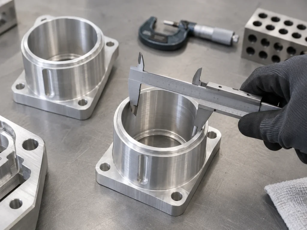
Check 3: preserve the reviewed drawing revision
Retain the released component file and the supplier’s marked proposal as identifiable records. The design team can then review the proposed local feature against the part that was actually requested.
When a clarification changes the model, record the disposition and the resulting drawing revision. Keep the quotation and later work instructions tied to that approved reference.
A note reading “boss accepted” needs its subject. Identify which feature, model and supplied condition the reviewer accepted. That short addition helps the next team recognize the scope of the decision.
If several housing variants share a similar body, keep their feature maps separate where the controlled drawings differ. Approval for one part should retain its original part and revision identity.
Use the extrusion and die-casting comparison when a project is still deciding its broader manufacturing route. A local feature review is most useful after the proposed route and component are identifiable.
Check 4: agree what the review record contains
Define the required evidence with the responsible quality and design teams. Connect the record to the supplied part, its revision and the specific requirement being checked.
A labeled photograph can support a location or appearance discussion. A dimension report can record its defined measurement. Keep each record’s subject clear rather than calling every attachment a complete component approval.
Ask for the applicable inspection definition where a requirement depends on the delivered surface. Include the relevant checking stage and the approved reference. Let the responsible reviewer resolve an undefined requirement before the order is released.
For an actual sample review, retain the sample identity and the resulting decisions. Our first-article inspection guide explains how to connect component evidence to the controlled drawing.
A fictional clarification: one face, two supplied stages
Imagine housing C36, revision D. The supplier’s marked model proposes contact feature EP2 on face S. The finished drawing also identifies face S as a required assembly interface.
Ask the supplier to identify the condition of face S at its quoted delivery stage. Then ask the designer to review EP2 against the final interface definition. Keep any later operation and its owner in the response.
Please identify EP2 on the revision D detail view. Confirm the supplied condition of face S and the later work included in this offer. Refer the proposed geometry to the responsible reviewer against the specified final interface.
This invented note organizes a drawing question. It contains no recommended boss size, permissible surface mark or actual tooling approval.
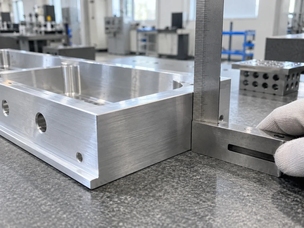
Connect the casting review to the assembly package
If the housing mounts to cut aluminum members, keep the casting reference and member list linked through the assembly drawing. Give the cutting team the actual section, finished member dimensions and required interfaces.
Identify which supplier owns the housing, its later operations and the member preparation. Each quotation should name its deliverable so the buyer can see how the finished assembly is supplied.
Send JiurunCut the defined aluminum member-cutting brief where that stage is part of the project. Keep die casting ejector pin bosses and casting-tool decisions with the confirmed foundry and responsible design team.
Can an unlabeled housing photo resolve the proposed feature?
Connect the image to the actual feature identifier, part revision and requirement being discussed.
Does a general explanation approve the boss geometry?
Use the project-specific proposal, responsible review and released component records.