
Aluminum casting draft angle describes a taper that must be interpreted with the specified die-opening direction. For a drawing review, connect the angle to the identified face and the plane at which a dimension applies.
A quotation saying only 2° draft leaves important geometry questions unanswered. Ask which faces it concerns, which direction defines the angle and how the proposed taper relates to the finished component.
This guide uses an invented cavity to explain a dimensional reading. The angle and dimensions in the exercise are not recommended casting design values or specifications for an actual part.
On this page
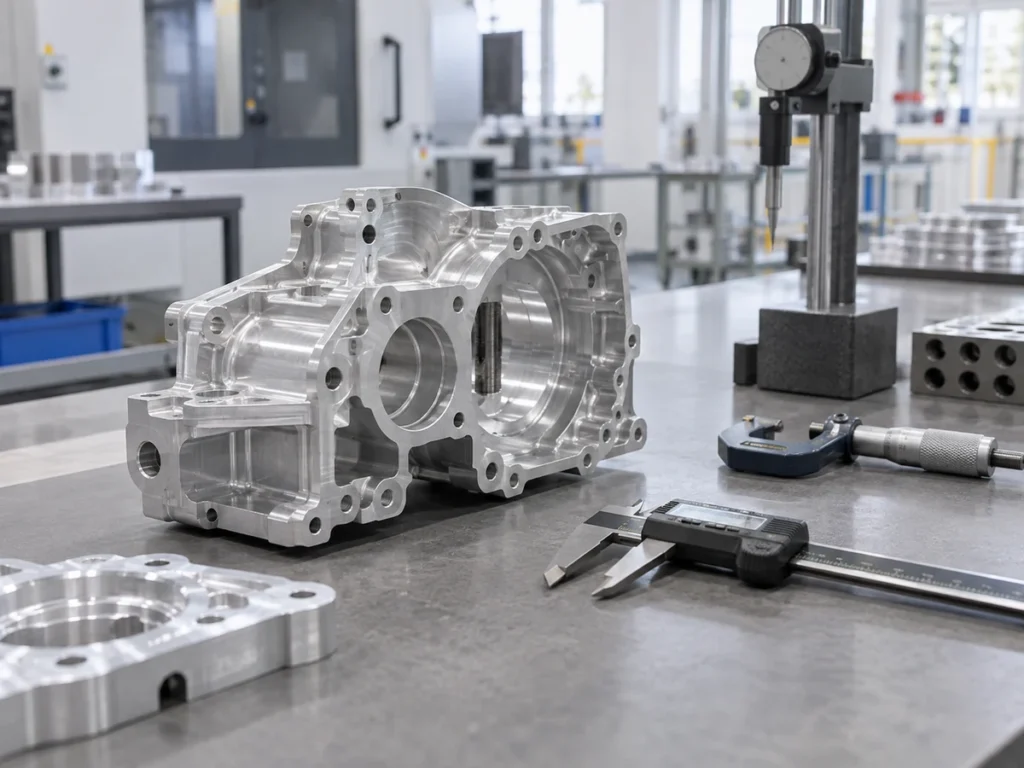
Check 1: connect the aluminum casting draft angle to its direction
NADCA Design’s draft explanation describes draft as taper on cores or other die-cavity features to help a casting eject. It relates the requirement to surfaces parallel with the die-opening direction.
The same explanation says the required angle varies with the wall or surface type, depth and alloy. It distinguishes the requirements of holes, inside walls and outside walls.
Those qualifications support a feature-specific review. Ask the actual foundry to identify its proposed draft on the current component model and drawing.
Mark the opening direction in the review view. Identify the face or group of faces affected by each proposed angle, with a section where the three-dimensional relationship is otherwise difficult to read.
Keep the angle definition beside that view. A dimension reviewer should not have to infer whether a short note refers to one wall, opposing walls or an entire opening.
If the supplier proposes changing the geometry, keep its marked proposal separate from the released component. Have the responsible design team review the proposed change and its effect on the specified features.
Check 2: name the plane at which the width applies
Imagine an ideal rectangular cavity with two straight opposing walls. In this fictional geometry, both walls widen outward toward the upper opening.
Assume a stated opening direction from the lower plane toward the upper plane. The planes are 50 mm apart along that direction, and each wall is tilted 2° away from it.
The invented width at the lower reference plane is 40 mm. This value belongs to that plane; it is not the width at every height in the cavity.
For one wall, the sideways offset across the stated 50 mm height is height multiplied by the tangent of the angle: 50 × tan(2°) ≈ 1.746 mm.
That is a right-triangle calculation for the invented straight wall. It does not determine the appropriate angle for a casting or approve any tooling arrangement.
Because both walls widen outward symmetrically, the total width increase is twice the one-wall offset: 2 × 1.746 ≈ 3.492 mm. The upper width is therefore approximately 40 + 3.492 = 43.492 mm.
Rounded to two decimal places, the invented upper width is 43.49 mm. Retain the rounding basis if that result is transferred into a review note.
| Defined item | Value in the exercise |
|---|---|
| Width at lower plane | 40 mm |
| Plane separation along opening direction | 50 mm |
| Angle of each wall from that direction | 2° |
| Calculated upper width | Approximately 43.49 mm |
The two width values describe different planes of the same invented shape. A bare note saying width 40 mm would lose that distinction.
For a real component, use the controlled model, sections and dimensional requirements. The simplified cavity contains no corner geometry, wall thickness, tolerances or tooling details.
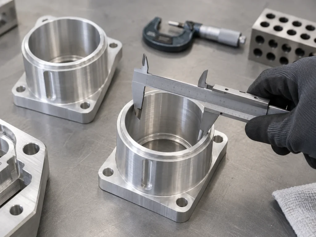
Check 3: distinguish one-face offset from total opening change
In the exercise, 1.746 mm belongs to one wall. Approximately 3.492 mm belongs to the increase across two outward-widening walls.
Keep those quantities separately labelled. Using the one-wall offset as the whole width change would describe a different geometry from the stated symmetric cavity.
The factor of two follows the invented symmetry assumption. It should not be carried into a real drawing whose opposing faces have different definitions or whose width changes in another way.
Likewise, retain the taper direction. The example explicitly widens toward the upper opening. Read the actual drawing and model to establish the relationship for another feature.
A clarification request can ask the foundry to identify the angle on each named face and confirm the width at each stated reference plane. This makes the answer more useful than repeating the same draft number.
Keep the geometric exercise separate from material identity. Our A356 designation guide addresses the material reference in a different purchasing field.
Check 4: resolve the actual delivered geometry
Identify which surfaces are supplied in the as-cast condition and which have later operations in the offer. Keep the finished-component requirements connected to the delivered-item description.
If the final feature requires a separate operation, name the party responsible and the agreed scope. Ask how the foundry’s proposed geometry connects to that downstream requirement.
Retain the component revision, alloy requirement and proposed production route in the review. Our extrusion and die-casting comparison addresses the broader route decision.
The sand-casting guide discusses a different mold arrangement. Keep a die-casting proposal identified by its own actual process and tooling records.
Ask the responsible designer and foundry to resolve affected fit, dimensions and inspection definitions before releasing a changed component. Keep open items visible in the quotation response.
An accepted draft proposal should identify exactly which model revision it applies to. A general explanation of draft does not approve every feature or establish a finished-part result.
A focused clarification for the drawing review
Please mark the opening direction and identify each face covered by the proposed draft. State the angle definition and the reference plane for each affected dimension. Identify the supplied condition, later operations and component revision covered by the offer.
Attach the relevant view and the supplier’s original proposal. When a response changes the component geometry, have the responsible reviewer disposition that change and retain the released records.
Quick questions before accepting the proposal
Does one draft number define all surfaces?
Ask for the feature-specific proposal and its identified geometry.
Is the example’s 2° a recommended design angle?
It is an invented input for explaining dimensions. Obtain the actual foundry and design-team review for a real component.
Does a width apply at every height of a tapered feature?
Keep the specified reference plane and model definition with the dimension.
Keep the defined stock-cutting stage clear
Send JiurunCut the identified aluminum stock and cut requirements when your project includes that supply stage. Keep aluminum casting draft angle and casting-tool decisions with the responsible foundry and design team.