
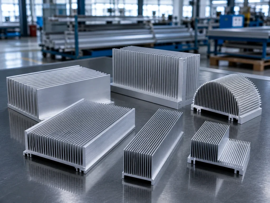
Heat sink fin spacing is the clear channel between neighboring fins. It is different from fin pitch, which describes the repeat distance between corresponding points on adjacent fins. Specify which dimension the drawing controls before comparing aluminum heat sink profiles.
For a buyer, the goal is to order the selected geometry consistently. More fins or a smaller gap does not, by itself, prove better cooling. Keep the supplied dimensions connected to the thermal owner’s approved configuration.
On this page
Heat sink fin spacing and pitch in plain language
Advanced Thermal Solutions’ fin-spacing article calls the gap a channel width. It explains that an excessively narrow channel can make it harder for air to pass through.
For a simple pattern of equally spaced, parallel fins, show the clear gap between facing surfaces. If the drawing uses pitch, show the corresponding repeat points. Fin thickness occupies part of that repeat distance.
With tapered, serrated or irregular fins, name the measurement location and references. A channel can have different local widths along its height. Do not assume a single photograph or an undefined “spacing” label captures the controlled geometry.
An ideal geometric example
Consider an invented cross-section with five straight, equal-thickness fins. Each fin is 2 mm thick. The clear gap between neighboring fins is 6 mm, and the base extends 3 mm beyond each outside fin.
Assume uniform rectangular fins with no taper or root-radius allowance for this arithmetic. These dimensions explain the terms; they are not recommended heat sink geometry, a production drawing or a JiurunCut specification.
| Term | Illustrative calculation |
|---|---|
| Clear gap | 6 mm between adjacent fin surfaces. |
| Pitch | 2 + 6 = 8 mm. |
| Width across the fins | 5 × 2 + 4 × 6 = 34 mm. |
| Overall base width | 34 + 3 + 3 = 40 mm. |
There are four interior channels between five fins. The two outer base margins are different features. They should not be counted as additional identical channels in this example.
The arithmetic establishes a nominal geometric relationship only. It predicts no temperature, airflow, thermal resistance or extrusion capability. Real profiles require their actual section details and tolerances.
If a supplier describes the gap as 8 mm when the drawing means an 8 mm pitch, ask for clarification. Even a small terminology mismatch can describe a different section. Resolve it before comparing prices or preparing a cut list.
Why more fins is not a cooling guarantee
Boyd’s heat sink selection guide relates planar-fin spacing to airflow velocity and fin length in the flow direction. It also explains that heat sink thermal resistance changes with external cooling conditions.
The purchasing implication is to identify the conditions behind the chosen section. Ask the thermal owner which geometry, orientation and airflow arrangement were assessed. Keep those details connected to the supplied part.
Do not select a denser profile by counting fins in two catalog pictures. An attractive increase in surface area is not a complete cooling assessment. The approved application needs its own engineering basis.
Use the passive versus active heat sink guide to identify the air arrangement. Use the thermal resistance guide when checking the performance definition and evidence.
Boyd also identifies extrusion geometry limits, including relationships between fin height, gap and thickness. Have the profile supplier review the actual section rather than treating an ideal arithmetic example as proof that a die can produce it.
Turn the selected geometry into a supplied-part drawing
Use the released section drawing or exact approved profile designation. Include the material requirement, finished cut length and any machining. Mark the base mounting surface and other functional references.
Identify the controlled gap or pitch, fin thickness and height at their specified locations. Preserve local features such as root radii or varying channels when they belong to the drawing. Avoid replacing the section with an outside width-by-height rectangle.
State the measurement stage where a later finish or operation affects the required dimensions. Keep the supplied condition clear: cut profile, machined heat sink or a further assembled component.
Provide the cut-length datum and orientation. Show which end and face reference later mounting features. The profile drawing and machining drawing should have compatible revisions.
Keep the cut direction separate from the section geometry. A transverse cut establishes the finished length; it does not intentionally change the repeated fin pattern. If another operation changes the fins, include it as identified work in the released route.
Agree the dimensional review
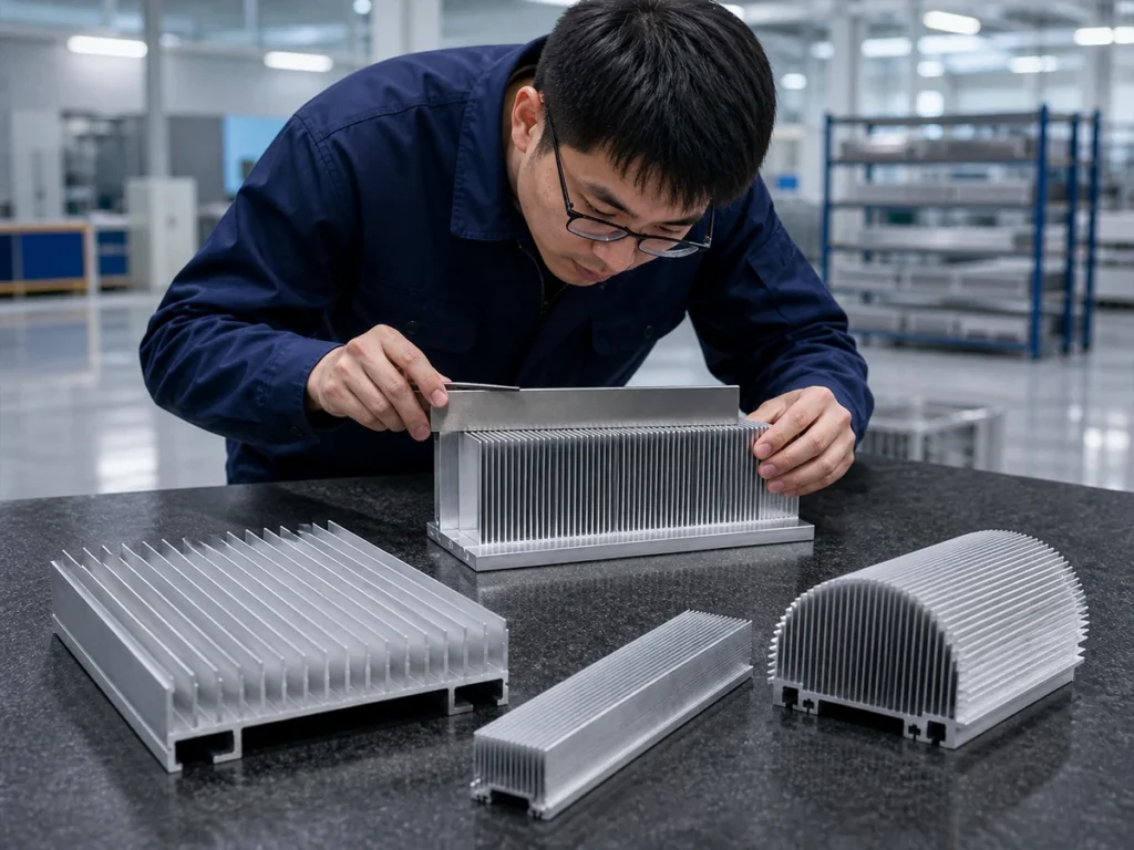
Before reviewing samples, specify the controlled locations, limits and suitable inspection method with the responsible team. An undefined request to “check every fin” gives no clear basis for acceptance.
Ask how the selected method reaches the relevant surfaces without changing the part’s condition. Keep the instrument identification and report references with the sample. The drawing determines what is measured; a convenient contact point should not silently replace it.
Separate three observations in the record: supplied dimensions, visible fin condition and performance evidence. A channel measurement supports a dimensional requirement. It does not establish the complete cooling result.
For cutting and handling, use the thin-fin cutting guide. Review the agreed support contacts and finished condition after collection, packing and normal transfer.
Review a substitute profile explicitly
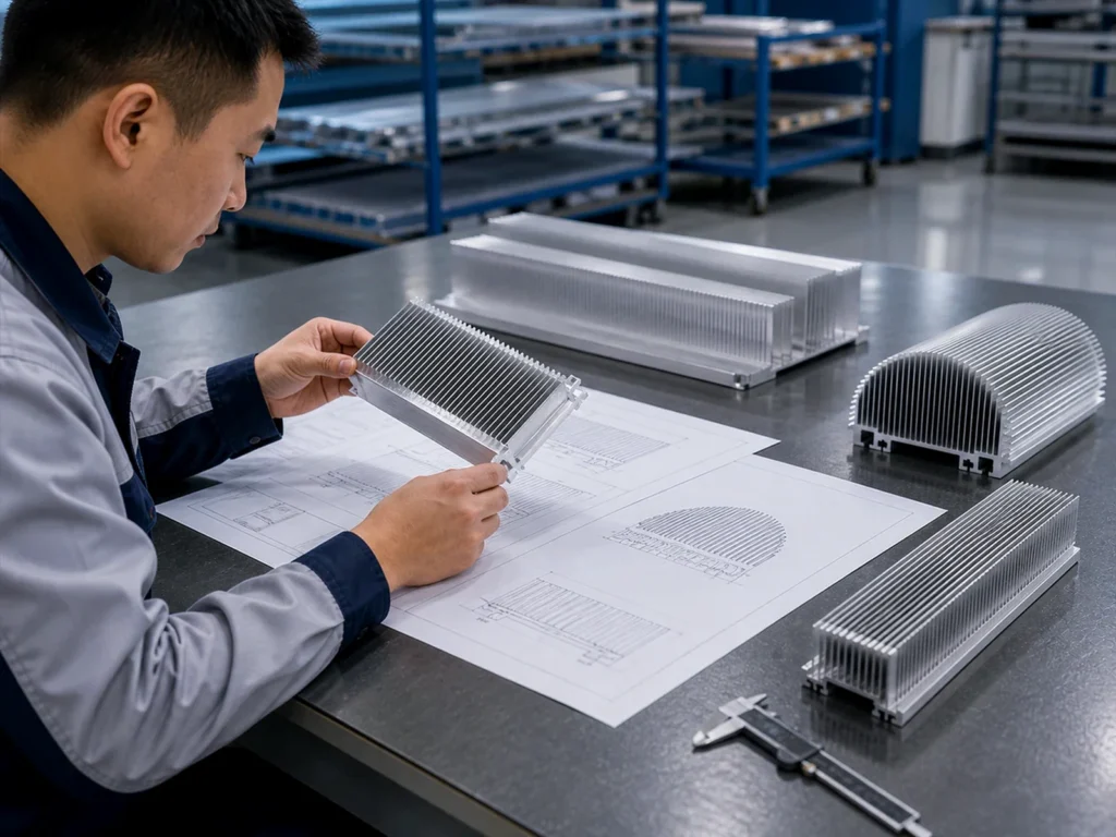
If a supplier proposes another section, request its exact drawing and identify every relevant change. Keep nominal outside dimensions separate from the fin pattern, base, mounting surfaces and delivery route.
Ask the thermal owner to decide which performance assessment must be updated. Ask the manufacturing owner to review cutting, machining and inspection implications. A substitute that fits the enclosure still needs those approvals.
Retain the accepted profile identity for repeat orders. When the drawing or finish changes, record the revision and any new sample review. Do not rely on a previous photograph to approve a later delivery.
Send JiurunCut the selected heat sink section and cut list to discuss the cutting stage. Include the fins, base, controlled surfaces and finished-part inspection requirements. Keep thermal selection and assembly validation with the responsible design team.
Buyer questions
Is fin spacing the same as fin pitch?
For the simple parallel pattern above, spacing is the clear gap and pitch includes one fin thickness. State the actual drawing references.
Are more fins always better?
The fin count alone does not establish performance. Compare geometry under the approved cooling conditions.
Can I order a heat sink from outside width and height?
Identify the full section and delivered condition. The fin pattern, base and functional surfaces also belong in the order.
Does a correct channel measurement approve cooling?
Keep dimensional acceptance and thermal evidence separately named. Each should satisfy its own defined requirement.