
Fan airflow vs static pressure matters when an aluminum heat sink works inside an enclosure. Two large catalog maxima do not describe one installed operating condition. To compare cooling proposals, ask how much air the selected fan moves against the resistance of the actual air path.
This guide explains the difference through three decisions and a simple fictional calculation. It helps buyers request the right evidence for a finned aluminum assembly. It does not select a fan, prescribe a heat load or establish the cooling capacity of the illustrated profiles.
On this page
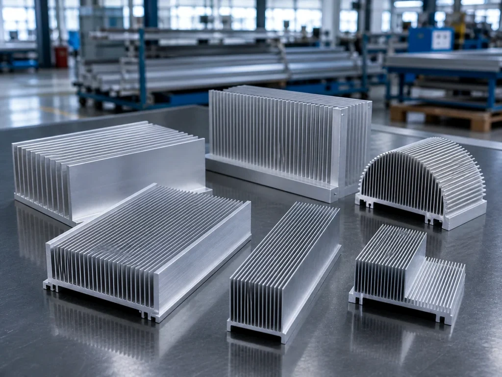
1. Separate the two maxima in fan airflow vs static pressure
A fan curve relates airflow and pressure under stated conditions. Its maximum airflow and maximum static pressure are different ends of that performance description. They should not be joined into a claim that the fan supplies both maxima simultaneously.
Noctua’s fan-curve comparison illustrates why endpoint rankings can differ from performance at the relevant operating points. It compares fan curves with sample resistance curves for a case, heat sink and radiator. Use that as a graph-reading example, not a recommendation of a particular fan for your industrial assembly.
Ask what the quoted number represents
When a supplier gives one airflow number, request its unit, operating condition and source. Identify whether it is a catalog endpoint, a prediction for the proposed system or a measurement in the assembled product.
Do the same for pressure. Keep the definition and unit beside the value. An unlabeled number copied into a quote makes it difficult to compare the same condition across suppliers.
If your project is still deciding whether to use driven air at all, start with the passive versus active heat sink guide. The curve review here addresses an arrangement that already includes a fan.
2. Find the operating point for the intended air path
NMB’s fan-selection paper connects the cooling air path, system pressure losses and the required operating point. It also describes airflow on the horizontal axis and static pressure on the vertical axis of the fan curve.
For a buyer, this becomes a request for two identified pieces of information: the selected fan’s performance curve and the resistance basis for the proposed layout. Ask the responsible engineer to identify the operating point used in the cooling review.
Keep the layout attached to the result
The relevant package should identify the enclosure, vents, heat sink arrangement and any other components included in that evaluation. Ask which drawing revision the result represents.
If the supplier changes the layout, keep the engineering response with the revised proposal. A previous result should not silently become approval of a different air path. Record what was assessed and what remains open.
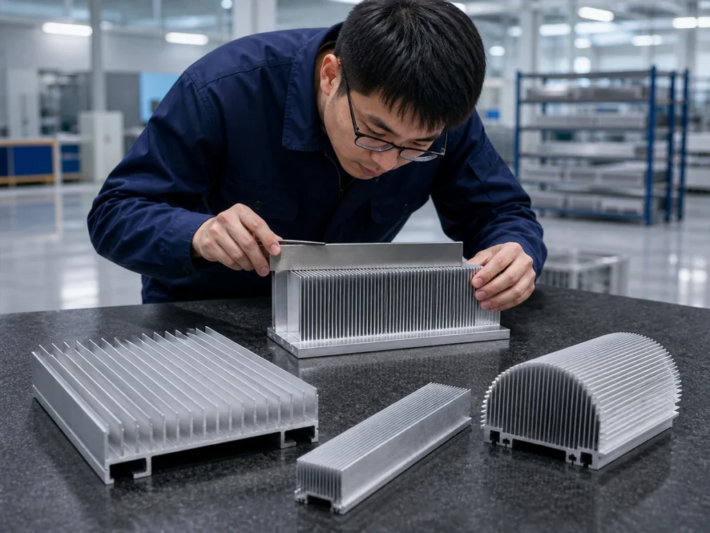
A fictional curve example: 60 does not mean 60 in the enclosure
The following equations and values are invented solely to illustrate an intersection. They are not manufacturer data, an engineering model of the pictured profiles or a recommended design. Real selection needs the applicable curves and system evaluation.
Let Q be the numerical airflow value in m³/h and P the pressure value in Pa. Define a simplified fictional fan curve as P = 120 − 2Q, for Q between 0 and 60. This chosen straight line has two endpoints: Q = 60 at P = 0, and Q = 0 at P = 120.
Now define a fictional system A by P = 0.20Q². At Q = 20, the fan equation gives 120 − 2 × 20 = 80 Pa. The system equation gives 0.20 × 20² = 80 Pa. The two chosen equations therefore meet at 20 m³/h and 80 Pa.
For a different invented system B, use P = 0.40Q². At Q = 15, the fan gives 90 Pa and the system also gives 90 Pa. The same fictional fan has a different intersection under that second assumption.
| Fictional condition | Airflow and pressure |
|---|---|
| Fan endpoint at zero pressure | 60 m³/h; 0 Pa |
| Fan endpoint at zero flow | 0 m³/h; 120 Pa |
| Intersection with system A | 20 m³/h; 80 Pa |
| Intersection with system B | 15 m³/h; 90 Pa |
The arithmetic explains the comparison error: neither installed intersection equals the free-flow endpoint of 60 m³/h. It does not predict a temperature, identify a sufficient airflow or prove that either fictional condition is acceptable.
Do not substitute this straight line for a real fan curve or these chosen system equations for measured resistance. The example is deliberately limited to reading two matching values at an intersection.
3. Request evidence for the complete assembly
Ask for the fan identification and the stated condition behind its curve. NMB’s paper identifies voltage and fan speed among the relevant curve information, and includes mechanical packaging and noise in the wider selection review.
Then request the thermal result for the proposed assembly under the project’s approved conditions. An airflow calculation and an acceptable component temperature answer different questions. The heat sink thermal resistance guide helps organize that separate performance evidence.
Make the purchase boundary explicit: a cut profile, a machined heat sink, an assembled sink and fan, or a complete cooling solution. Assign responsibility for the supporting drawings and acceptance evidence before comparing prices.
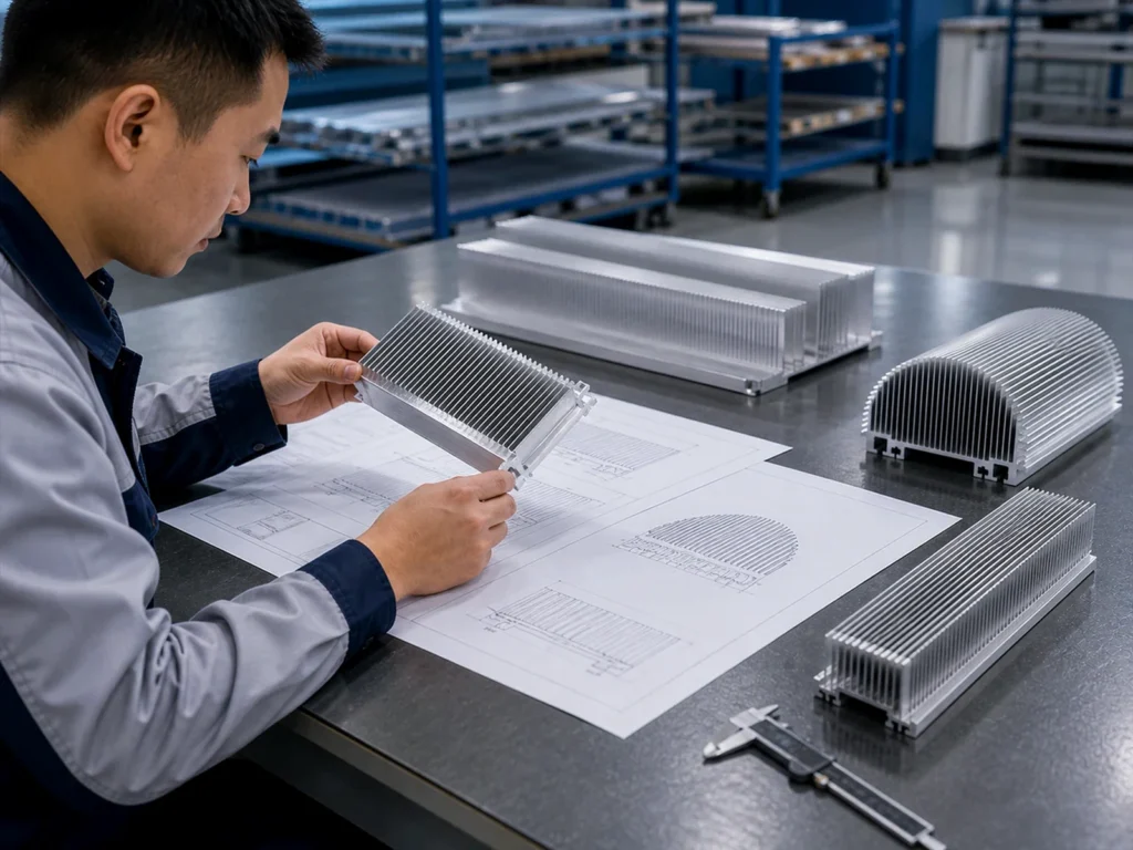
Connect the review to the aluminum part definition
After the responsible designer selects the cooling arrangement, provide the controlled section, finished length, mounting features and surface requirements for manufacturing. Keep that drawing revision connected to the accepted assembly.
Use the thin-fin cutting guide to discuss support and handling. A correctly cut part supports the component drawing; it does not replace the system’s thermal approval.
Common buyer questions
Should I choose the largest maximum airflow?
Request a comparison at the intended system operating condition. A single endpoint does not settle the complete purchase.
Does an operating point prove the heat sink will meet the temperature limit?
It is one input to the evaluation. Request the applicable thermal evidence and the project’s acceptance decision.
Can I reuse a result after changing the enclosure?
Identify the changed layout and ask the responsible engineer which parts of the previous assessment remain applicable.