
Aluminum welding distortion belongs in the project handoff before cut blanks are accepted for a welded assembly. The finished length of an individual member and the final geometry of the welded product are different inspection stages.
Give each supplier a clear description of what they deliver, which drawing applies and when the dimensions are checked. This helps the buyer coordinate cutting, welding and any subsequent machining without assigning every final-assembly requirement to the saw-cut blank.
On this page
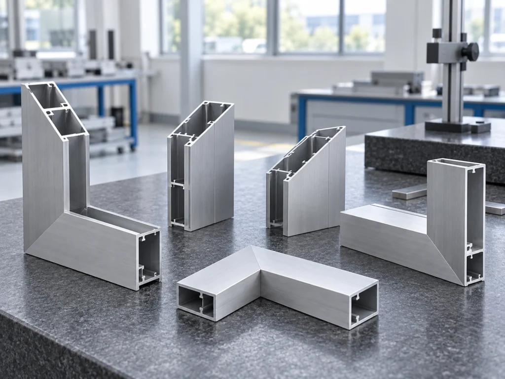
Aluminum welding distortion: why the stage matters
TWI’s explanation of distortion describes stresses associated with local thermal expansion and cooling contraction around a weld. If those stresses exceed the parent material’s yield strength, localized plastic deformation can alter dimensions permanently.
TWI’s weld-material distortion overview identifies aluminum as particularly susceptible. It describes forms including lengthwise and transverse shrinkage, angular change, twisting and bowing.
The purchasing task is to make the required condition explicit. Ask the responsible fabricator or engineer how the planned process addresses the final drawing. A general statement that the cut lengths are correct does not establish the geometry after joining.
Our heat affected zone guide covers the separate material-condition questions. A dimensional review and a material-property review should each retain their own acceptance basis.
Stage 1: accept the cut blanks against their own drawing
Start the cutting inquiry with the stock identity, drawing revision, member lengths, end angles and quantities. Describe the datum and measurement convention used for the cut piece.
State whether the listed length is the blank dimension or a dimension belonging to the final assembly. If the drawing does not make that distinction clear, have the responsible reviewer resolve it before the production cutting list is released.
Where a later operation needs an allowance, obtain the approved value and its purpose from the process owner. Keep it in the released documentation. Do not add a guessed shrinkage allowance to every member because the product will eventually be welded.
Record the cutting inspection result as a result for that piece and stage. Our finished-length datum guide helps keep the measurement reference clear.
Stage 2: define the assembly fit-up review
Identify the assembly drawing, member orientation and joint requirements used by the fabricator. Keep matching parts and their revisions traceable so the assembly team can check that it has the intended kit.
TWI’s distortion overview includes joint design and preparation, procedure selection, sequence selection and fixtures among the areas addressed in distortion prevention. These choices belong in the responsible welding review rather than an improvised purchasing instruction.
Ask which fit-up checks the fabricator will record and which conditions will be carried into welding. Keep the accepted setup connected to the final inspection plan.
If the team finds a gap or misalignment, record the condition and refer it to the process owner. Changing an end angle or shortening a member during assembly should follow an approved disposition and revised record.
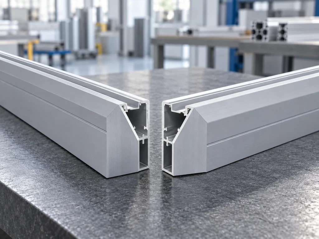
Stage 3: review the welded condition against a defined requirement
Agree which dimensions, angles and geometric features are checked after welding. Identify the assembly condition and measurement references so the inspection result can be understood without guessing.
Ask the fabricator to explain the process basis for controlling distortion. TWI’s overview also discusses modelling and prediction; it shows that process planning can involve evaluating a complete welding sequence and its constraints.
A buyer can request that explanation without prescribing a welding recipe. Keep decisions about restraint, welding sequence and any corrective process with the responsible technical authority.
The public abstract of ISO 13920:2023 covers general tolerances for welded structures, including linear and angular dimensions, shape and position. It describes four tolerance classes selected according to functional requirements and states that the applicable tolerances are those in the drawing.
The same abstract notes that complex structures may require special provisions. ISO lists the 2023 edition as published when checked on October 1, 2026. Use the actual drawing, applicable complete document and responsible reviewer; this guide does not supply a tolerance table or select a class.
Stage 4: identify the final delivered condition
List any machining, finishing or approved correction that occurs after welding. Identify whether final acceptance takes place before or after those operations.
A mounting surface might have one requirement in the welded state and a different requirement after an approved machining step. Make the deliverable condition explicit so both the supplier and receiving team inspect the same thing.
Keep inspection records tied to the assembly identity and revision. If a correction is proposed, request its approved disposition and the required reinspection. Do not describe a corrected part as accepted while the relevant review remains open.
For a measurement plan involving flat surfaces, our flatness versus parallelism guide explains why those feature requirements need separate labels.
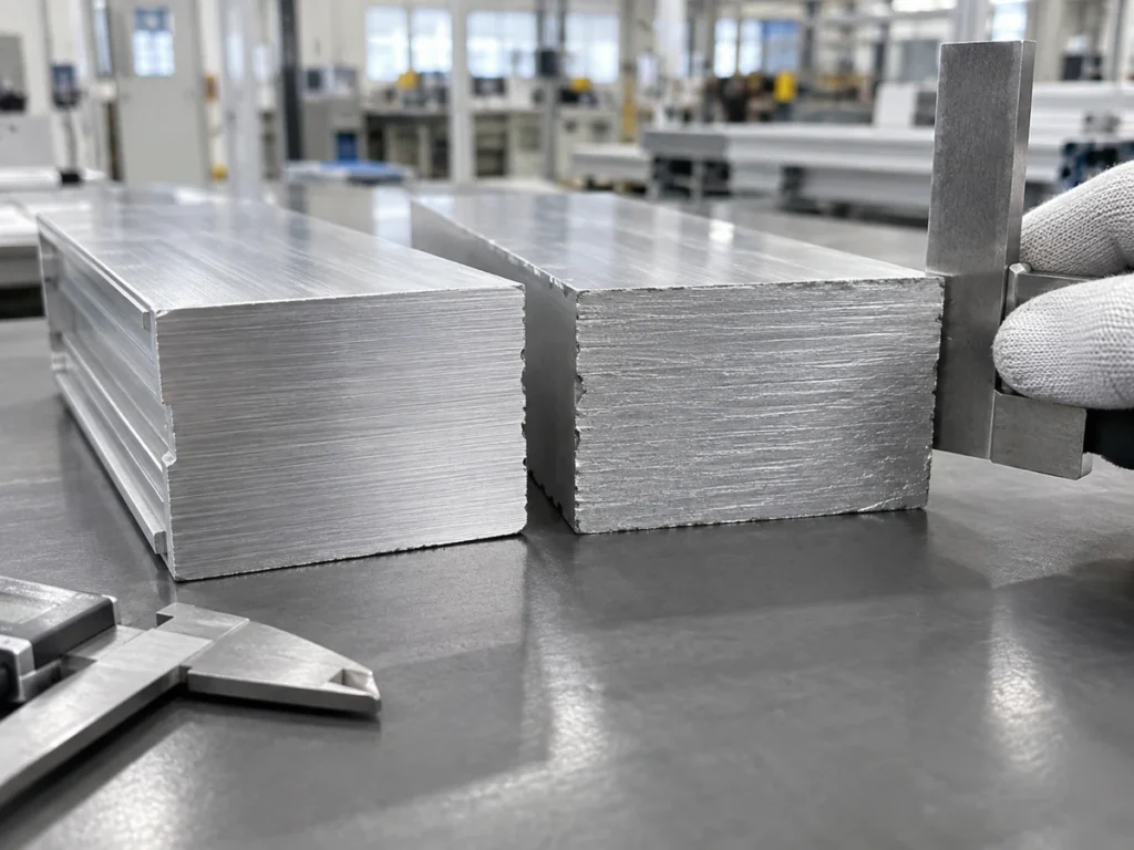
Compare the scope of two offers
The following is a hypothetical procurement example, not a JiurunCut customer result. One offer supplies cut members; another offer supplies a welded and subsequently machined assembly.
Both may reference a final assembly drawing, but their accepted deliverables are different. Ask each supplier to identify the stage and scope included in its price and supporting inspection record.
| Deliverable offered | Acceptance question |
|---|---|
| Cut members | Which blank dimensions, datums, end details and handling requirements apply? |
| Welded assembly | Which welded-state dimensions and geometry are evaluated? |
| Finished assembly | Which subsequent operations and final inspection condition are included? |
Keep any excluded operation visible. A lower cutting price and a finished-assembly price need a scope comparison before the buyer can draw a useful conclusion.
Send JiurunCut your profile drawing and cutting list for a discussion of the cut-part arrangement. Mark the cutting deliverable clearly and retain the approved downstream requirements in the project handoff.
Questions buyers ask
Can correct cut lengths guarantee final weldment dimensions?
No. Check the final assembly at the agreed stage against its own drawing and inspection requirements.
Should buyers add one general shrinkage allowance?
Use the allowance approved for the actual process and documented part. A guessed universal adjustment does not establish the finished geometry.
Does citing ISO 13920 select the tolerance class?
The drawing and technical review need to identify the applicable requirements. A standard number by itself does not settle every acceptance question.
Can purchasing choose a straightening method?
Request a disposition from the responsible technical authority, then preserve the approved process and reinspection requirements in the record.