
Choose rivet nuts for aluminum from the complete joint requirement, not the screw size alone. Identify the approved fastener, local grip thickness, prepared hole, head and body geometry, installation access and acceptance evidence. Have the fastener supplier review the representative component before production release.
“Aluminum rivet nut” can describe the fastener material. “Rivet nut for an aluminum part” describes the receiving component. Specify both so the quotation answers the intended request.
Keep these separate on the drawing
- The screw thread is not the installation-hole size.
- The local grip thickness is not the profile’s overall depth.
- The fastener catalogue does not approve the complete assembled joint.
On this page
Rivet nuts for aluminum: identify the complete fastener
Start with the approved manufacturer and part number when the design already specifies one. Include the thread designation, fastener material, finish, body form, head style and open or closed end. Keep proposed alternatives visibly separate.
Böllhoff’s RIVKLE overview describes blind rivet nuts for thin-walled components and hollow profiles, including applications accessible from one side. Its standard range includes different materials, heads, body forms and end configurations.
This product variety makes a complete identifier useful. Two offers with the same thread can still describe different installation requirements or mating-face arrangements. Do not accept a substitute by matching only the thread label.
Describe the joint purpose to the responsible reviewer: which component is retained, how it is assembled and which requirements govern the connection. If loads or service conditions need approval, obtain that review before releasing the fastener selection.
Specify the aluminum component’s material and finish as separate information. Where the joint includes different metals, use the galvanic-corrosion purchasing review to document the full interface and exposure. Do not assume that an aluminum receiving part requires an aluminum fastener in every design.
A rivet nut also differs from a tapped hole or another insert system. The guide to threaded-insert purchasing requirements covers other insert decisions. Keep the selected installation method explicit in this order.

2. Match the grip range to the local joint thickness
Identify the thickness at the actual installation location. For a hollow section, show the wall receiving the fastener. The outside height of the section is a different dimension and does not describe the material being gripped.
Where the approved design clamps more than one layer, identify those layers and their finished condition. Use the intended assembled thickness for the fastener review, with any relevant variation documented.
Ask the fastener supplier to check the selected grip range against the actual material, hole and installation arrangement. Provide the thickness requirement and representative samples rather than relying on a nominal stock description.
Sherex by PEM’s CAL aluminum catalogue states that parent material and hole size can affect grip range, and recommends trial installations for the application. Its individual items list thread, grip range and hole size separately.
The catalogue supports reviewing the actual joint; it does not supply a universal range for every aluminum extrusion. Use the selected fastener’s current data and the approved trial result for the order.
For mixed profile families, identify any different wall conditions as separate joint locations. A successful installation in one section should not silently approve another section with a different local thickness or internal feature.
3. Define the prepared hole and head seating face
Use the installation-hole geometry from the approved fastener data. Show its size, form and location on the component drawing, together with the relevant tolerance and final acceptance stage.
The internal screw thread and the outside installation hole serve different purposes. A thread designation cannot replace the prepared-hole callout. Confirm that the hole requirement matches the exact body version being supplied.
Identify the head seating face and any required preparation. Show whether the mating component must clear a projecting head or sit against a specified recessed arrangement. Review the fastener drawing with the assembled joint view.
Locate the hole from defined part features. When an edge or corner is close, ask the responsible technical reviewer to establish the permissible layout for that fastener and component. Do not borrow an edge-distance rule from a different joint system.
State the accepted hole-edge and surface condition. If drilling, deburring or finishing occurs at different suppliers, identify who delivers the prepared installation feature. Keep the receiving stage clear.
Use the hole-position drawing review for component references and dimensions. That drawing control supports the fastener review but does not replace its installation specifications.
4. Review installation access and the mating screw
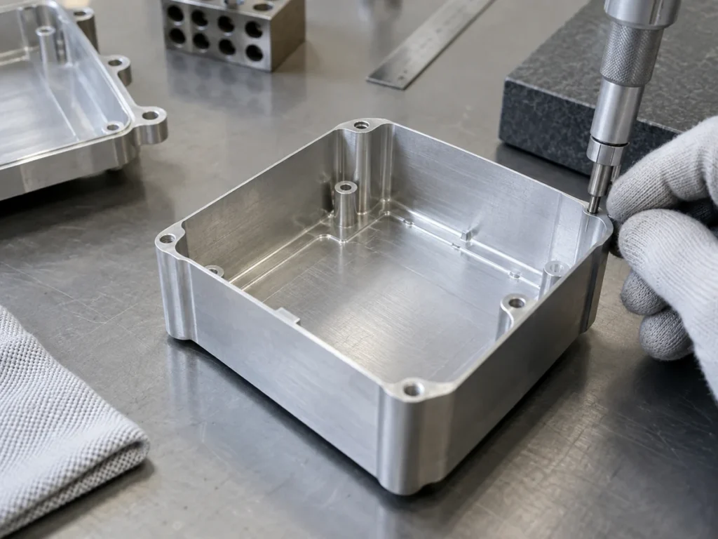
Provide a section view where access is restricted. Identify internal webs, opposite walls and nearby features that may affect the proposed installation. Ask the setting-tool supplier to review the actual receiving face and available space.
Böllhoff describes the set rivet nut as clamping the component between its head and a formed area of its body. This explains why the wall and space behind it belong in the application review, even for a process accessed from one side.
Confirm tool access at the planned production stage. Installation before an enclosure cover is fitted and installation after assembly may have different access conditions. Show the sequence in the order.
Specify the approved mating screw and the assembled stack. Have the responsible reviewer establish engagement and clearance requirements, including any closed-end limit. A screw that matches the thread designation is not automatically the correct assembled length.
Keep screw tightening requirements separate from rivet-nut setting requirements. The two operations have different purposes. Obtain their respective approved instructions rather than copying a single torque value into both steps.
If sealing is required, identify the complete joint requirement and supporting evidence. An end configuration or marketing description alone does not establish the enclosure’s accepted sealing performance.
5. Agree installation ownership and acceptance evidence
Identify who installs the fastener and which approved equipment and instructions apply. Ask that supplier to review the selected component and perform the agreed trial before a production commitment.
Böllhoff refers users to its product catalogue for the appropriate setting force for the selected dimensions. Follow the exact fastener and tool documentation. This article is a purchasing checklist, not an installation procedure or universal setting specification.
Define the acceptance checks with the responsible technical reviewer. They may include fastener identity, seating, thread condition and required joint tests. Specify the method, criteria and records when testing forms part of the order.
Keep the sample connected to its part revision, material, fastener identifier and installation route. A photograph without those references cannot explain which configuration was reviewed.
When a hole, wall thickness, fastener version or installation route changes, identify the affected joint and request the required review. Record the accepted revision before the new configuration enters production.
| RFQ field | Reference to provide |
|---|---|
| Fastener | Approved identifier, thread, material and body/head version |
| Receiving part | Drawing revision, local thickness and finish |
| Installation | Prepared hole, access review and agreed instructions |
| Acceptance | Representative sample and specified checks |
Questions that stop a quote release
The offer gives only a thread size. Request the complete fastener identifier and proposed installation requirements before accepting the component preparation or hardware line.
The drawing shows overall section depth, but no local wall. Identify the receiving wall in a section view and provide the applicable thickness requirement for the grip-range review.
The supplier proposes a different body shape. Review the installation hole and assembled interface with the proposed data. Keep the alternative unapproved until the responsible review is recorded.
The order says “test passed” without a configuration. Ask which component, fastener, installation route and acceptance criteria the evidence covers. Request the missing connection to the actual delivery.

Cutting and machining handover
Supply the profile drawing, cut lengths and quantities along with the next-operation references. Identify the finished datum used for the prepared-hole position and the faces needing protection during handling.
State whether the cutting supplier delivers blanks or completed installation features. Assign drilling, deburring, coating and fastener installation to the agreed production stages so scope is visible in each quotation.
Send JiurunCut your cutting list and profile drawing with the intended downstream joint locations. Keep fastener selection, installation approval and joint acceptance within the agreed technical responsibility.
Buyer questions
Are rivet nuts for aluminum always made from aluminum?
No. Specify the approved fastener material separately from the aluminum receiving part and review the complete joint.
Does the screw size define the installation hole?
No. Use the prepared-hole requirement for the exact approved rivet nut version.
Can I use the profile’s overall depth as grip thickness?
Identify the local material or approved layer stack being gripped at the installation location.
Does a catalogue load value approve my assembly?
The responsible reviewer must establish the joint requirements and application evidence. A general product value does not approve an unspecified component configuration.