
Aluminum cutting gauges can provide a defined pass/fail check for a part feature, but the result is only useful when the gauge matches the drawing, the inspection setup and the required part condition. A “GO” result is not a complete dimensional report for every feature on the component.
For repeat batches of profiles, tubes or frame members, decide what the inspection must establish before asking for a fixture or limit gauge. These five acceptance checks help buyers discuss the requirement with their supplier and quality team.
Start with the feature, then the tool
- Name the drawing feature and its limits before selecting the gauge.
- Define how the part is located, prepared and assessed.
- Record the gauge identity and the actual scope of the result.
On this page
1. Match aluminum cutting gauges to a named feature
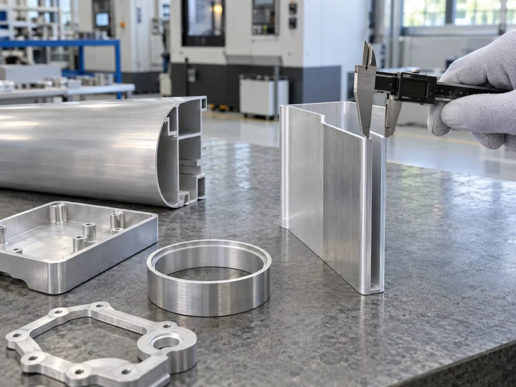
Write the part number, drawing revision and feature identification in the inspection request. Specify whether the question concerns finished length, a section dimension, a machined feature or a particular functional relationship.
KEYENCE describes limit gauges as tools for inspecting finished dimensions and distinguishes function gauges for maximum material condition. Its overview shows why different gauge types serve different checks. See KEYENCE’s explanation of limit and function gauges.
A simple size check and a functional check are not interchangeable. Ask a qualified gauge designer or metrology specialist to interpret the complete drawing, including any datum references and applicable geometric requirements. Do not treat the word “gauge” as a universal inspection method.
For a mitered member, identify the required length definition before discussing a fixture. A long-point length and a short-point length can describe different features. Use your miter-length convention consistently in the drawing and inspection instruction.
If several parts share a similar appearance, list which part variants the gauge is approved to assess. Similar external profiles do not establish that one gauge covers every drawing revision or handed version.
2. Agree the part condition and inspection setup
The instruction should show where the part sits and which surfaces locate it. Identify the intended orientation, contact areas and support arrangement. Where a datum scheme is required, keep it consistent with the drawing rather than substituting a convenient surface.
State the inspection stage. A saw-cut blank, a deburred blank, a drilled part and a finished coated component can represent different states in the manufacturing route. Record the state that the approved inspection is intended to assess.
Ask the quality team to define preparation and handling requirements. Chips, residual material or damage at a contact area should not be hidden by an unclear instruction. Equally, staff should not alter a part merely to make it fit a gauge.
For a thin-wall or flexible section, have the specialist review support and contact effects. A fixture that changes the part’s shape needs careful evaluation against the intended requirement. This article does not prescribe a contact force or fixture design.
Use a clear work instruction with identified views and contact features. A photograph can help explain orientation, but it should accompany the approved method rather than become an informal replacement for it.
3. Confirm gauge identity, revision and status
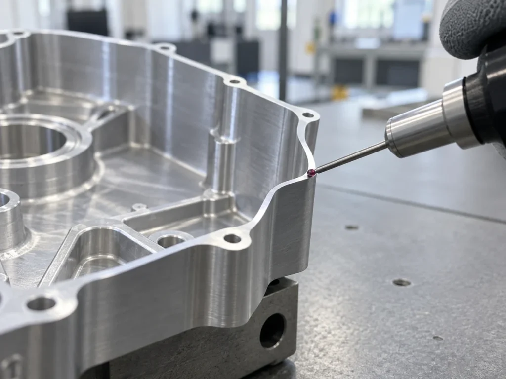
Give the gauge an identification that can be recorded beside the part result. Keep its approved drawing or specification revision, applicable part list and operating instruction together. An unnamed fixture on a bench is difficult to trace after a disagreement.
Request the appropriate calibration or verification records and have the quality team review their relevance to the intended check. NPL explains calibration as a comparison with a recognized standard and provides services that support measurement traceability. See NPL’s calibration guidance.
A dated label alone does not describe every characteristic of a custom fixture. Ask which features were assessed, what the record covers and whether the identified tool is suitable for the proposed acceptance task.
Agree the site’s controls for damage, wear, storage and rechecking. The interval and checks should come from the responsible quality system and technical review. Do not assume this article sets a universal calibration frequency.
When the part drawing changes, review the gauge’s applicability as part of the revision process. Keep the change record linked to the current cutting documentation, so an old tool does not silently become the acceptance method for a new requirement.
4. Decide whether pass/fail information is enough
A defined limit-gauge check can answer whether a feature passes its approved test. It may not provide the numerical measurement needed for an inspection report, a process trend or a comparison between trial runs.
Ask what the customer needs to receive. If the requirement includes measured lengths with units, an entry that only says “pass” does not supply those values. Conversely, do not invent a dimension from a successful gauge check.
Keep numerical measurement and pass/fail assessment separate in the record. A numeric result also needs the identified method, reference features and relevant uncertainty review; simply adding a digital display does not settle those questions.
When choosing between a gauge and a measuring instrument, start with the required information and review the complete measurement task. Your caliper resolution review can help distinguish a displayed increment from evidence of measurement suitability.
A drawing change needs a gauge review
Consider a fictional part whose inspection instruction names gauge G-01 for drawing revision A. The customer then releases revision B with a changed feature requirement. No gauge review has yet been recorded.
| Known information | Required clarification |
|---|---|
| G-01 is identified for revision A. | Does its approved specification also cover the changed requirement in revision B? |
| A part from the new revision fits the existing tool. | Does that observation represent the approved test for the current drawing? |
| The gauge has a calibration record. | Is the record relevant to the feature and method now required? |
The example does not establish acceptance or rejection. It identifies missing evidence. A passing observation with an old tool should not be relabeled as approval of the new drawing without the responsible review.
5. Keep the full part-release decision complete
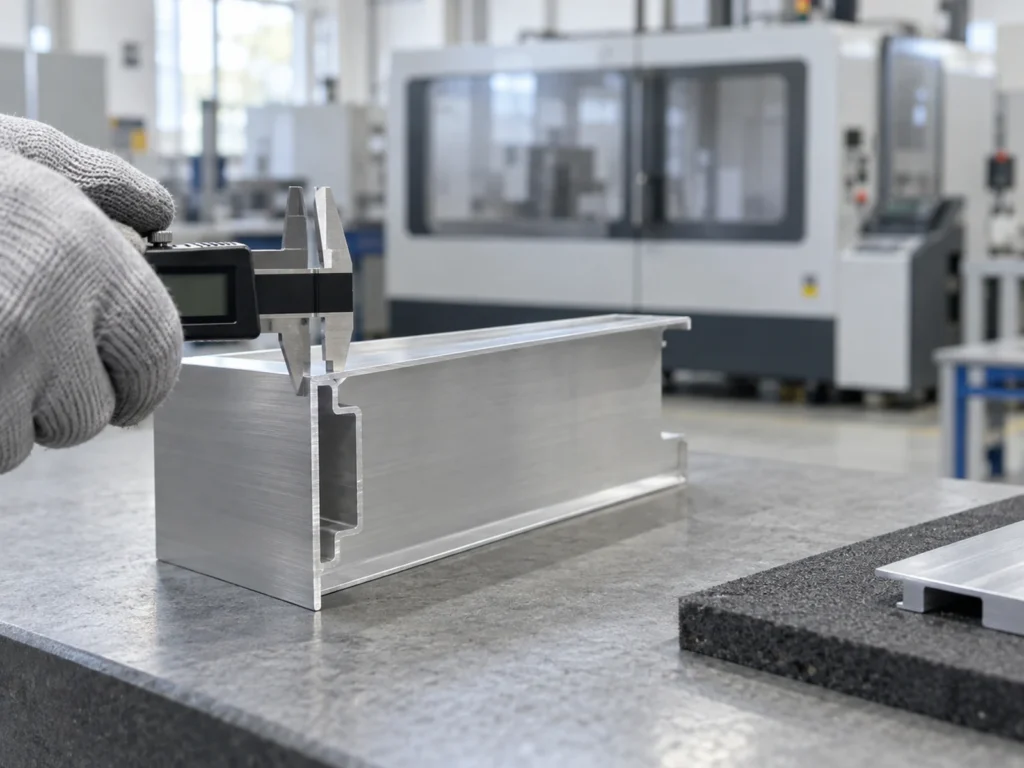
List which drawing requirements the gauge covers and which require other inspection. A size check does not automatically document cut-face quality, surface damage, material identity or every hole location.
Define what happens after a failed or unclear check. Identify the responsible reviewer and the record used for further assessment. Keep parts awaiting a decision distinguishable from released parts through your normal quality procedures.
For a sample-cutting trial, agree the gauges, measurement records and part identification before reviewing results. This lets the buyer compare the actual trial evidence with the requested features rather than relying on a general claim that the parts “fit.”
Retain the approved instruction and results with the batch records. The useful evidence is the identified part checked by the identified method, at the required stage, against the current requirement.
Prepare a useful cutting inquiry
Send the full drawing, material description, finished lengths and batch mix. Identify the critical acceptance features and attach any approved gauge specification already used by your quality team.
Ask what trial parts and records are needed to review the proposed cutting process. If gauge design is still open, state that clearly so the inquiry does not imply an agreed method that does not exist.
Send JiurunCut your profile drawing and inspection requirements to review the cutting job and the evidence needed for a sample assessment.
Buyer questions about aluminum cutting gauges
Does passing a gauge prove every dimension is correct?
No. The result covers the approved test. Keep other drawing requirements in the inspection plan.
Can a gauge result be written as an exact measured dimension?
Do not create a numerical value from pass/fail information. Use an appropriate measurement and record when numerical results are required.
Can one gauge cover every similar-looking profile?
Only use it for the parts and revisions covered by its approved specification and inspection method.
What should accompany the result?
Record the part and drawing identity, gauge identity, relevant instruction, inspection stage and the actual result. Keep any unresolved applicability question visible.